
|
28.559 bytes |
Service Hints & Tips |
Document ID: GKEY-3H4HNA |
PCServer704 - Diagrams (Front Panel)
Applicable to: World-Wide
Front Panel Control Board
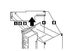
1. Remove the two screws.
- The board is now held in place by a pop-on/off snap.
2. Hold the board by the top edge or upper corners.
- Pull it slightly toward the back of the chassis to release the snaps.
- Carefully lift it up and out of the chassis.

|
1. |
J14, power cable to the liquid crystal display (LCD), 3-pin connector |
|
2. |
J12, signal cable to the LCD 14-pin connector |
|
3. |
J5, signal cable to intrusion switch at back corner above the power supplies, 3-pin connector |
|
4. |
J11, signal cable to system board, 40-pin connector (pin 17 removed) |
|
5. |
J2, signal cable to intrusion switch at back corner above board cage area, 3-pin connector |
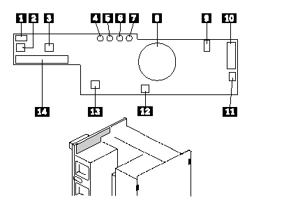
Front Panel Control Board Interface

|
1. |
Signal from C2 switch at back edge near card cage 3-pin right-angle latching-style connector. |
|
2. |
Power switch |
|
3. |
Reset switch |
|
4. |
Power-on LED, green |
|
5. |
Power-fail LED, amber |
|
6. |
Cooling-fail LED, amber |
|
7. |
Drive-fault LED, amber |
|
8. |
Speaker |
|
9. |
Signal from intrusion switch at back edge near power supplies 3-pin right-angle latching-style connector |
|
10. |
Signal interface to the LCD 14-pin straight-head connector |
|
11. |
Power to the LCD 3-pin straight-head connector latching-style connector |
|
12. |
Hard drive bay C2 switch |
|
13. |
NMI switch |
|
14. |
Signal interface to system board 40-pin straight-head connector (pin 17 removed) |
|
Search Keywords |
| |
|
Hint Category |
Hardware Maintenance Information | |
|
Date Created |
15-05-97 | |
|
Last Updated |
28-05-98 | |
|
Revision Date |
27-05-99 | |
|
Brand |
IBM PC Server | |
|
Product Family |
PC Server 704 | |
|
Machine Type |
8650 | |
|
Model |
Various | |
|
TypeModel |
| |
|
Retain Tip (if applicable) |
| |
|
Reverse Doclinks |