

|
87.965 bytes |
Service Hints & Tips |
Document ID: GKEY-3H4DAA |
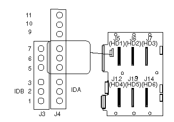
PCServer704 - Diagram (Backplane Connectors)
Applicable to: World-Wide
Backplane Connectors
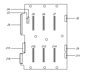
|
J2 |
LED cable connector for drives 1, 2, 3 |
|
J3,J4 |
Drive ID and configuration jumper blocks |
|
J5 |
Wide SCSI bay drive 1 |
|
J6 |
Wide SCSI bay drive 2 |
|
J7 |
Wide SCSI bay drive 3 |
|
J8 |
Narrow SCSI cable, output |
|
J9 |
LED cable connector for drives 4, 5, 6 |
|
J10 |
Power and ground from power distribution board and power supply |
|
J11 |
IC bus connector |
|
J12 |
Wide SCSI drive bay 4 |
|
J13 |
Wide SCSI drive bay 5 |
|
J14 |
Wide SCSI drive bay 6 |
|
J15 |
Wide SCSI cable connector, input from channel A or B |
SCSI Drive ID, J3 and J4
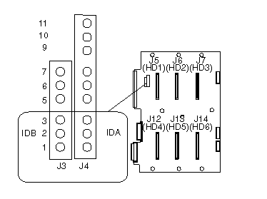
|
Jumper |
Pins |
SCSI |
ID |
of |
Drive | ||
|
J3,IDA |
J4,IDB |
HD |
HD |
HD |
HD |
HD |
HD |
|
1 |
2 |
3 |
4 |
5 |
6 | ||
|
1-2 |
1-2 |
0 |
1 |
10 |
3 |
4 |
13 |
|
1-2 |
2-3 |
0 |
1 |
2 |
3 |
4 |
5 |
|
2-3 |
2-3 |
8 |
9 |
2 |
11 |
12 |
5 |
|
2-3 |
1-2 |
8 |
9 |
10 |
11 |
12 |
13 |
SCSI Flash Update Jumper, J4
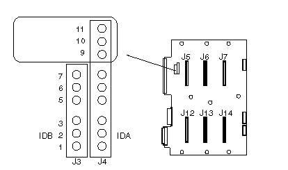
|
Jumper Pins |
Description |
|
10-11 |
Reserved |
|
9-10 |
Normal |
|
Factory |
default setting. |
External Backplane Jumper
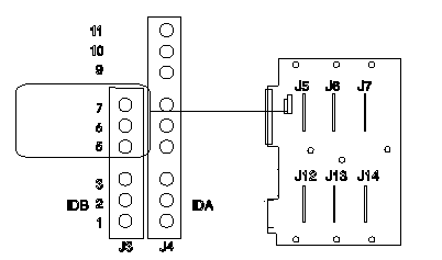
|
Jumper Pins |
Description |
|
6-7 |
Reserved |
|
5-6 |
Internal backplane (backplane is installed in the server) |
|
Factory |
default setting. |
Secondary Jumper, J4
|
Note | |
|
When more than one backplane is installed in the server, the backplane in the upper position is jumpered as primary and the backplane in the lower position is jumpered as secondary. |
|
Jumper Pins |
Description |
|
6-7 |
Secondary |
|
5-6 |
Primary |
|
Factory |
default setting. |
|
Search Keywords |
| |
|
Hint Category |
Hard Drives, Hardware Maintenance Information | |
|
Date Created |
15-05-97 | |
|
Last Updated |
22-01-99 | |
|
Revision Date |
27-05-99 | |
|
Brand |
IBM PC Server | |
|
Product Family |
PC Server 704 | |
|
Machine Type |
8650 | |
|
Model |
Various | |
|
TypeModel |
| |
|
Retain Tip (if applicable) |
| |
|
Reverse Doclinks |