
|
118.874 bytes |
Product Information |
Document ID: DDSE-46VQFV |
Netfinity 5500 - System Board Component Locations and System Board Jumpers
Applicable to: World-Wide
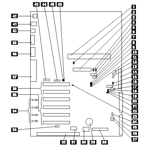
System Board Component Locations
The following illustration shows the system board and identifies system-board components. You might need to refer to this figure before you install hardware in your server, or when you record information in the tables in this chapter. You might also need to refer to this figure when you set configuration jumpers on the system board.
|
1 |
Processor board connector (J19) |
|
2 |
System management processor error LED (CR24) |
|
3 |
RAID channel 1 connector (J7) |
|
4 |
RAID channel 1 error LED (CR30) |
|
5 |
RAID channel 2 error LED (CR31) |
|
6 |
Reserved (J54) |
|
7 |
Reserved (J64) |
|
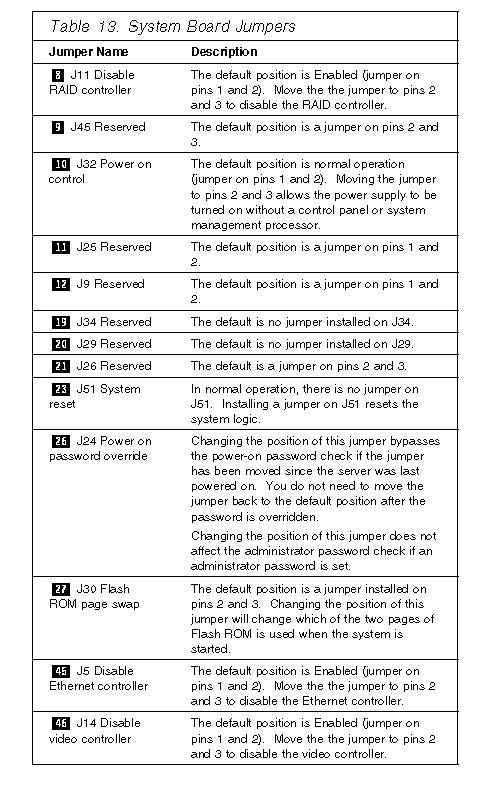
8 |
Disable RAID controller jumper block (J11) |
|
9 |
Reserved (J45) |
|
10 |
Power on control jumper block (J32) |
|
11 |
Reserved (J25) |
|
12 |
Reserved (J9) |
|
13 |
Power backplane cable connector (J8) |
|
14 |
RAID channel 2 connector (to backplane) (J3) |
|
15 |
RAID system error LED (CR32) |
|
16 |
Reserved (J27) |
|
17 |
Reserved (J35) |
|
18 |
SCSI activity LED connector (J52) |
|
19 |
Reserved (J34) |
|
20 |
Reserved (J29) |
|
21 |
Reserved (J26) |
|
22 |
IDE connector (J33) |
|
23 |
System reset jumper block (J51) |
|
24 |
Fan connector (J36) |
|
25 |
Diskette drive connector (J22) |
|
26 |
Power on password override jumper block (J24) |
|
27 |
Flash ROM page swap jumper block (J30) |
|
28 |
Control panel connector (J20) |
|
29 |
Battery |
|
30 |
Reserved (J46) |
|
31 |
Hot-plug PCI controller programmer interface |
|
32 |
ISA expansion slot |
|
33 |
Hot-plug switch connector (J16) |
|
34 |
PCI slot LEDs (four are on the side of the board) |
|
35 |
PCI Slots 1-4 (hot-plug) |
|
36 |
PCI Slots 5 and 6 |
|
37 |
Parallel port connector (J56) (Serial port A and B |
|
38 |
Video port connector (J2) |
|
39 |
Management port C connector (J42) |
|
40 |
USB 1 and USB 2 port connectors (USB 2 is |
|
41 |
Mouse and keyboard connectors (J1) (The |
|
42 |
Ethernet port connector (J4) |
|
43 |
Reserved (J17) |
|
44 |
Reserved (J18) |
|
45 |
Disable Ethernet controller jumper block (J5) |
|
46 |
Disable video controller jumper block (J14) |
|
Note |
|
Search Keywords |
| |
|
Document Category |
Diagrams | |
|
Date Created |
12-04-99 | |
|
Last Updated |
21-05-99 | |
|
Revision Date |
12-04-2000 | |
|
Brand |
IBM PC Server | |
|
Product Family |
Netfinity 5500 | |
|
Machine Type |
8660 | |
|
Model |
| |
|
TypeModel |
| |
|
Retain Tip (if applicable) |
| |
|
Reverse Doclinks |