
|
379.531 bytes |
Service Hints & Tips |
Document ID: DDSE-3R7JB9 |
|
This document is provided to IBM and our Business Partners to help sell and/or service IBM products. It is not to be distributed beyond that audience or used for any other purpose. |
Server Options - 3518 Locations
Applicable to: World-Wide
Locations:
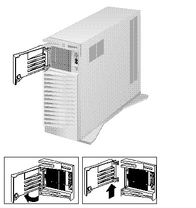
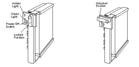
DASD Door:
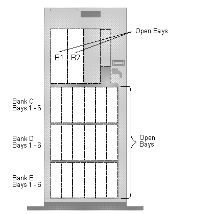
Expansion Bays:
|
Bays/Banks |
Supported Devices |
|
Bays B1 and B2 |
CD-ROM drives, internal SCSI hard disk drives, or tape drives |
|
Banks C, D, and E |
Up to 18 SCA, hot-swap, 3.5-inch hard disk drives |
Front Cover:
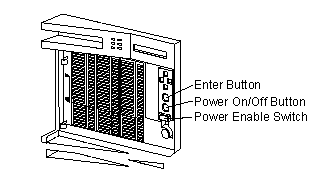
Front Panel Controls:
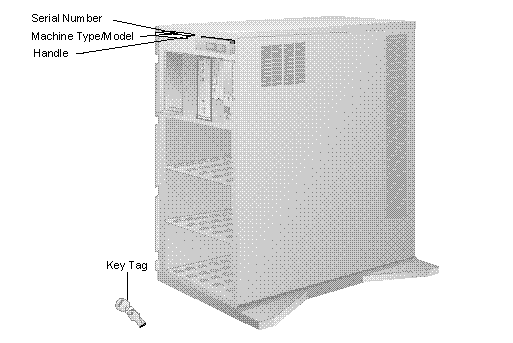
Identification Numbers:
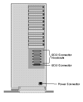
Input/Output Connectors:
Note:
The following illustration shows the rear view of the Type 3518 Expansion Enclosure.
Hot Swap Backplane (FRU No. 06H8629):
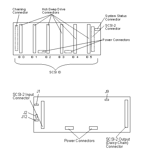
J12 Backplane SCSI ID Jumper Settings:
The Backplane SCSI ID Address Jumper, a pin block with four pairs of pins (J12), is located on the rear of the backplanes in banks C, D, and E. When two backplanes are daisy-chained in the enclosure, the first backplane address jumper (for example, Bank C) must be set to LO, defining the SCSI IDs as 0 through 5. The second backplane (in this example, bank D), must be set to either
Reverse, defining the SCSI IDs as 5 through 0, or HI, defining the SCSI IDs as 8 through D. The default, no jumper installed, is to set the addresses to LO.
If the SCSI adapter supports more than eight SCSI devices per SCSI channel, the second backplane can be set either HI or Reverse. However, if the SCSI adapter supports eight or less SCSI devices per channel, the second backplane must be set to Reverse.
The following jumper settings are for SCSI ID jumper J12.
Hot Swap Tray (FRU No. 06H8631, 07H0774):
Notes:
1. The following trays are shown with drives installed.
2. Each hot-swap drive installed must have a Hot Swap Drive Tray attached.
The Hot Swap Drive Tray for the expansion enclosure has a small switch that stops the movement of the disk drive. The tray also provides two LEDs (one green and one amber) to indicate the current state of the drive and tray. The following table summarizes the LED states on the hot-swap tray and their meanings.
|
Green |
Amber |
Description |
|
On |
Off |
The Drive tray is powered on; the hard disk drive is inactive; and the drive should not be removed. |
|
Blinking |
Off |
The hard disk drive is inactive. The hot-swap drive can be removed safely. |
|
On |
On or Blinking |
The hard disk drive is in use, and should not be removed. |
|
Off |
Off |
The drive is defective, or no power is being supplied to the drive. The hot-swap drive can be removed safely. |
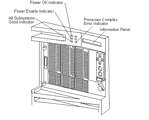
Front Panel LED Status Indicators:
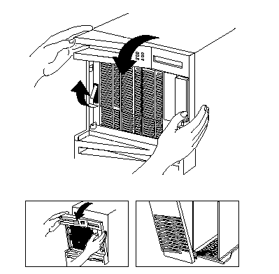
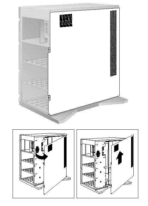
Side Cover:
System Board:
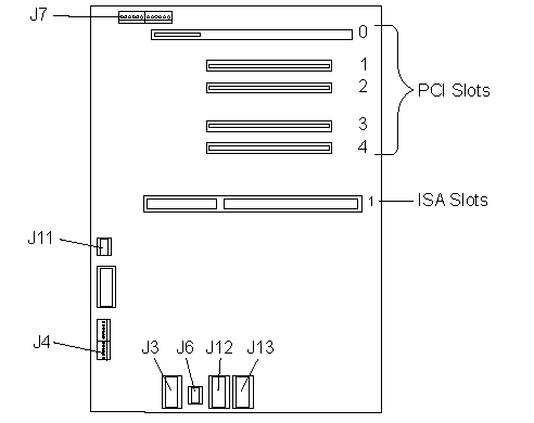
System Board Connections:
|
Connector |
Description |
Connect To |
|
J3 |
Power Supply Connector |
P1 |
|
J6 |
Power Supply Connector |
P3 |
|
J7 |
Operator Panel Connector |
Operator Panel |
|
J12 |
Power Supply Connector |
P2 |
|
J13 |
Power Supply Connector |
P2A |
Note:
The following slots/connectors on the system board are not currently supported.
|
Slots/Connectors |
Description |
|
PCI Slot 0 |
64 Bit PCI connector |
|
PCI Slots 1 to 4 |
32 Bit PCI connectors |
|
ISA Slot 1 |
System Maintenance Adapter for Reporting Trouble (SMART) ISA Card |
|
J11 |
C2 Security Connector |
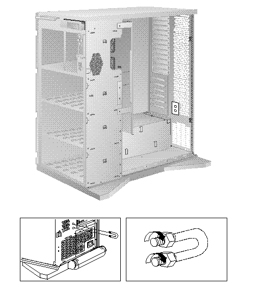
U-Bolt Security (Optional):
|
Search Keywords |
| |
|
Hint Category |
Hard Drives, Hardware Maintenance Information | |
|
Date Created |
07-10-96 | |
|
Last Updated |
22-01-99 | |
|
Revision Date |
28-04-99 | |
|
Brand |
IBM PC Server | |
|
Product Family |
Rack/Storage Enclosures | |
|
Machine Type |
3518 | |
|
Model |
| |
|
TypeModel |
| |
|
Retain Tip (if applicable) |
N/A | |
|
Reverse Doclinks |