
|
122.809 bytes |
Product Information |
Document ID: MCGN-42EK2X |
Netfinity 7000 M10 - Working with Adapters
Applicable to: World-Wide
Source: Hardware Maintenance Manual
You can add adapters to extend the capabilities and power of your server. Many adapters provide bus-master capabilities, which enable the adapters to perform operations without interrupting the server's microprocessors. You add adapters to the expansion connectors, called slots, on the I/O board of your server. All slots are peripheral component interconnect (PCI) expansion slots. Your server supports up to 12 adapters in the PCI slots.
You can install a new PCI adapter or replace an existing PCI adapter with the same type of adapter without turning the server power off and restarting the system. These slots are called hot-pluggable PCI slots. They are also referred to as hot-plug PCI slots. Hot-plug requires support from both the operating system and the adapter device driver.
A PCI adapter comes with built-in identification and configuration specifications (set in memory on the device) that provide installation information to the server during startup. This information is read by the input/output (I/O) bus and interpreted by the server BIOS. The BIOS routines automatically configure the adapter around the resources already in use by other devices.
Your server comes with a video controller. This video controller is an integrated component on the I/O function card. The integrated video controller has super video graphics array (SVGA) technology.
The integrated video controller is not removable. If you want to disable this controller and use a video adapter instead, you can install a video adapter in an expansion slot. When you install a PCI video adapter, the server BIOS automatically disables the integrated video controller.
The integrated video controller has 1 MB of video memory. The integrated video controller supports the following screen resolutions:
640 x 480 pels with up to 65,536 colors
800 x 600 pels with up to 65,536 colors
1024 x 768 pels with up to 256 colors
1152 x 864 pels with up to 256 colors
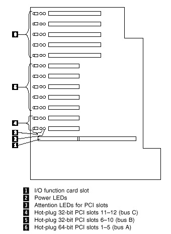
The following illustration shows the location of the expansion slots and other components referred to in these steps.

LEDs for PCI Slots: Each PCI slot has three lights associated with it - two Attention lights and one Power On light.
- Power On Light: This light is on when the PCI slot is active and has power. Do not add or remove an adapter from the PCI slot when the Power On light is on. When this light is off, the PCI slot is inactive and has no power applied. You can install or remove an adapter when the Power On light is off. Refer to your operating system documentation to determine if it supports hot-plug PCI adapters.
- Attention Lights: Each PCI slot has two Attention lights: one that is visible from the rear of the server and one that is visible inside the server. (The lights have the same meaning; they are duplicated to be visible from outside or inside the server.) An Attention light flashes approximately once per second when it is on. The meaning of the Attention lights is defined by your operating system. Refer to your operating system documentation to determine if it supports hot-plug PCI adapters and, if so, what the Attention lights indicate.
Adapter Considerations: Before you continue with the adapter-installation procedure:
- Review and follow the instructions that come with the adapter and your operating system in addition to the instructions given in this chapter. If you need to change the switch or jumper settings on your adapter, follow the instructions that come with the adapter documentation.
- You can install full-length PCI adapters in all PCI expansion slots.
- Your server supports only 5.0 V DC PCI adapters.
- Your server uses a rotational interrupt technique to configure PCI adapters. This technique enables you to install a variety of PCI adapters that currently do not support sharing of PCI interrupts.
- For a list of compatible RAID adapters, and installation requirements, refer to http://www.pc.ibm.com/us/compat/
on the World Wide Web. If you install a RAID adapter, configure the adapter using the RAID adapter documentation.
- The I/O function card slot can support only the I/O function card. It is not an expansion slot.
- The system-management adapter slot can only support the Advanced Remote Management Controller. It is not an expansion slot.
- Your server has three 33 MHz PCI buses.
- PCI slots 11 and 12 are on PCI bus C (bus numbers 0 and 1, with bus numbers 2 and 3 reserved for adapters that require bus number assignments).
- PCI slots 6-10 are on PCI bus B (bus number 4, with bus number 5-9 reserved for adapters that require bus number assignments).
- PCI slots 1-5 are on PCI bus A (bus number 10, with bus numbers 11-15 reserved for adapters that require bus number assignments).
- You can install 32-bit adapters in 64-bit slots and 64-bit adapters in 32-bit slots.
- Spread the installation of high speed adapters, such as Gb Ethernet adapters, between the three PCI buses to optimize performance.
Configuring Adapters: PCI devices automatically communicate with the server configuration information. This usually results in automatic configuration of a PCI device. From the Configuration/Setup Utility program, you can select available resources for the adapter that you are installing. If a conflict does occur, see "Resolving Configuration Conflicts".
Refer to the documentation that comes with the adapter for information about required system resources. Then, make the appropriate jumper or switch settings on the adapter.
Installing a Hot-Plug PCI Adapter: This section gives the procedure for installing a hot-plug PCI adapter. If you want to remove a hot-plug adapter, reverse the steps. If your operating system supports hot-replace PCI adapters, you can replace a failing hot-plug PCI adapter with a new adapter of the same type without turning off power to the server. If your operating system and adapter also support the hot-add feature, you can install a new adapter without turning off the power to the server.
|
Note |
|
Before you begin: |
|
Attention |
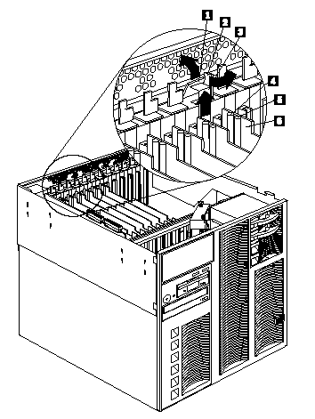
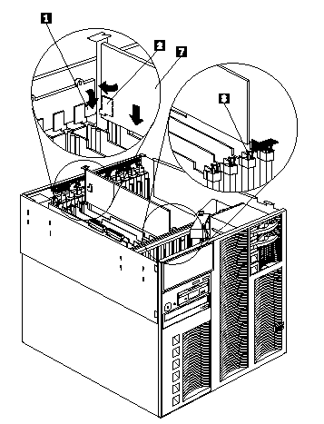
Refer to the following illustrations while you perform the steps in this procedure.

1 Tab
2 Adapter retention latch
3 Expansion slot cover
4 Attention light
5 Power light
6 Plastic divider

1 Tab
2 Adapter retention latch
7 Adapter
8 Adapter retention latch
To install a hot-plug PCI adapter:
1. Remove the top cover (see "Removing the Top Cover").
2. Determine which expansion slot you will use for the adapter.
|
Note |
3. Disable the PCI slot from your operating system.
(Refer to the documentation that comes with your operating system for information about disabling a hot-plug PCI slot.)
Attention: Make sure the Power On light 5 for the expansion slot is off before you continue with the next step. Failure to do so might cause your system to lock up.
4. Remove the expansion-slot cover 3 :
a. Rotate the adapter retention latch 2 .
b. Lift the tab 1 covering the top of the expansion-slot cover 3 and remove the expansion-slot cover from the server. Store it in a safe place for future use.
Attention: Expansion-slot covers must be installed on all vacant slots. This maintains the electromagnetic-emissions characteristics of the system and ensures proper cooling of system components.
5. Refer to the documentation that comes with your adapter for any cabling instructions. It might be easier for you to route any cables before you install the adapter.
6. Remove the adapter from the static-protective package.
|
Note |
|
Note |
Installing a Non-Hot-Plug PCI Adapter: This section gives the procedures for installing a non-hot-plug adapter. If you want to remove a non-hot-plug adapter, reverse the steps.
Before you begin:
- Read "Safety Information".
- Read the documentation that comes with your adapter for any special requirements or restrictions.
Refer to the illustrations in "Installing a Hot-Plug PCI Adapter" while you perform the steps in this procedure.
To install a non-hot-plug PCI adapter:
1. Run the shutdown procedure for the operating system. Turn off the server and peripheral devices and disconnect all external cables and power cords (see "Preparing to Install Options"); then remove the top cover (see "Removing the Top Cover").
2. Determine which expansion slot you will use for the adapter.
|
Note |
|
Note |
|
Attention |
|
Search Keywords |
| |
|
Document Category |
Diagrams | |
|
Date Created |
20-11-98 | |
|
Last Updated |
18-01-99 | |
|
Revision Date |
18-01-2000 | |
|
Brand |
IBM PC Server | |
|
Product Family |
Netfinity 7000 M10 | |
|
Machine Type |
8680 | |
|
Model |
all | |
|
TypeModel |
| |
|
Retain Tip (if applicable) |
| |
|
Reverse Doclinks |