

|
198.674 bytes |
Parts Information |
Document ID: DDSE-42ZPX7 |
Netfinity 5500 - Using the ServeRAID Monitoring Functions
Applicable to: World-Wide
Using the ServeRAID Monitoring Functions:
This section contains instructions for using the ServeRAID Administration and Monitoring utility program to monitor the ServeRAID controller status information, event logs, logical drive information, and physical device information.
Monitoring Status Information: You can monitor the ServeRAID controller status by clicking on the active ServeRAID controller button on the Main Screen of the Administration and Monitoring utility program. The currently active ServeRAID controller button is indicated by a green or red light. (Green indicates an active controller; red indicates that the controller is not responding.)
If there is more than one ServeRAID controller in the system, click on the appropriate button to make it active.
A screen similar to the following appears.
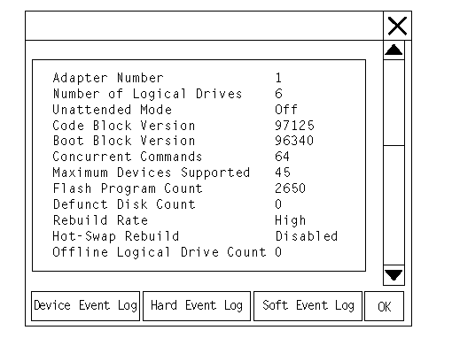
Descriptions of the information that appears on the screen are as follows.
Note
You might have to scroll down, using the scroll bar, to see all of the items that appear on this screen.
|
Adapter Number |
The active ServeRAID controller (1 to 8). |
|
Number of Logical Drives |
The number of defined logical drives (0 to 8). |
|
Unattended Mode |
Off - The user chooses the recovery method when there |
|
Code Block Version |
The current version level of the firmware microcode for |
|
Boot Block Version |
The current version level of the microcode loaded in |
|
Concurrent Commands |
The maximum numbers of concurrent commands |
|
Maximum Devices Supported |
The maximum number of devices supported. |
|
Flash Program Count |
The number of times that the ServeRAID controller |
|
Defunct Disk Count |
The current number of defunct hard disk drives. |
|
Rebuild Rate |
The setting for the rebuild rate can be low, medium, or |
|
Hot-Swap Rebuild |
If hot-swap rebuild is set to enable, the ServeRAID When you replace the drive and these requirements |
|
Offline Logical Drive Count |
The current number of offline logical drives. |
|
Configuration Update Count |
The number of times that the ServeRAID controller |
Monitoring Event Logs: The ServeRAID controller stores, in the event logs, information concerning various unexpected events. There are three types of event logs: a device event log, a hard event log, and a soft event log.
To view the event logs:
1. Click on the adapter (or controller) on the Main Screen of the Administration and Monitoring utility program.
A screen similar to the following appears.
2. Select the appropriate button at the bottom of the screen for the event log you want to view.
Device Event Log: The Device Event Log contains event counters for each attached physical device.
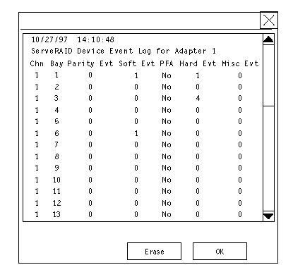
Descriptions of the events logged in the Device Event Log are as follows:
- Parity Event
The ServeRAID controller detects parity events while transferring data on the SCSI bus. A large number of parity events might indicate a problem with the SCSI cable, connectors, or terminators attached to the devices.
- Soft Event
SCSI devices detect these events and reports them to the ServeRAID controller through Check Condition status.
- Predictive Failure Analysis (PFA)
A device has signaled the ServeRAID controller that it might fail in the near future.
- Hard Event
The ServeRAID controller detects these events. Most likely, these events are caused by the ServeRAID controller.
- Misc Event
The ServeRAID controller detects these events. Most likely, these events are caused by the SCSI device, such as selection timeout, unexpected bus free, or SCSI phase event.
|
Note |
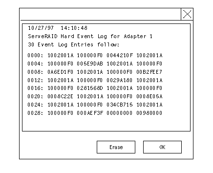
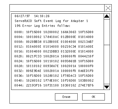
Hard Event Log: You can view the Hard Event Log.
Soft Event Log: You can view the Soft Event Log.
Monitoring the Logical Drive Information:
You can monitor the logical drive information by clicking on the desired logical drive button on the Main Screen of the
Administration and Monitoring utility program.
When you click on the logical drive button, a screen similar to the following appears.
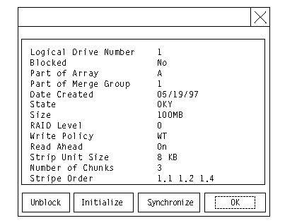
are as follows:
|
Logical Drive Number |
The number of the logical drive. |
|
Blocked |
No - The logical drive is accessible. |
|
Part of Array |
The identifier of the logical drive's disk array |
|
Part of Merge Group |
The identifier of the logical drive's merge |
|
Date Created |
The date that the logical drive was created. |
|
State |
The current drive state (see "Logical Drive States"). |
|
Size |
The size in megabytes. |
|
RAID Level |
RAID level (0, 1, or 5). |
|
Write Policy |
WT - Write-through. |
|
Read Ahead |
Off - Disk Read-Ahead is inactive. |
|
Stripe Unit Size |
The size of each stripe unit per hard disk (8, 16, 32, 64). |
|
Number of Chunks |
The number of hard disk drives that make up |
|
Stripe Order |
The channel and bay number of the physical drives that |
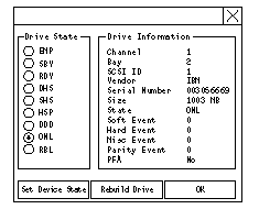
Descriptions of the information that appears on this screen are as follows:
|
Channel |
The channel to which the device is connected. |
|
Bay |
The bay number of the device on a channel (1 to 16). |
|
SCSI ID |
The SCSI ID (0 to 15). |
|
Vendor |
The drive manufacturer. |
|
Serial Number |
The drive manufacturer's identifier. |
|
Size |
The size of the drive in megabytes. |
|
State |
The current drive state (see "Physical Device States" and |
|
Soft Event |
The number of soft events reported from the |
|
Hard Event |
The number of hard events reported from the |
|
Misc Event |
The number of miscellaneous events reported |
|
Parity Event |
The number of parity events reported from the |
|
PFA |
Yes - Device indicates predictive failure analysis event. |
Configuring the Ethernet Controller
Your Netfinity 5500 comes with an Ethernet controller on the system board. The Ethernet controller provides 10BASE-T and 100BASE-TX support through the RJ-45 connector on the back of your server. When you connect your server to the network, the Ethernet controller automatically detects the data-transfer rate (10 Mbps or 100 Mbps) on the network and then sets the controller to operate at the appropriate rate. That is, the Ethernet controller will adjust to the network data rate, whether the
data rate is standard Ethernet (10BASE-T), Fast Ethernet (100BASE-TX), half duplex (HDX), or full duplex (FDX). This process is also known as auto-negotiating. This auto-negotiation occurs without requiring software intervention. The controller supports half-duplex (HDX) and full-duplex (FDX) modes at both speeds.
|
Note |
Fast Ethernet operates at a data rate of 100 Mbps; that is, ten times faster than standard Ethernet. However, except for the different operating speeds, Fast Ethernet and standard Ethernet are structurally identical. Applications and protocols that are currently hosted on a standard Ethernet system can be seamlessly migrated to a Fast Ethernet system. (In a very small number of cases, minor tuning might be required to adjust the application to the higher performance of a Fast Ethernet system). Because of the equivalence of the two types of Ethernet, mixed Ethernet and Fast Ethernet systems also can be designed and implemented.
The bandwidth required at each workstation connected to a server is generally far less than the bandwidth required at the server. This is because the server might have to handle the bandwidth of multiple workstations at the same time. A cost-effective solution to the bandwidth requirements of this type of system is a mixed Ethernet and Fast Ethernet network. This mixed network consists of standard Ethernet connections at the workstations and Fast Ethernet connections at the servers.
The Ethernet controller is a PCI device, and is therefore, a Plug and Play device. You do not have to set any jumpers or configure the controller for your operating system before you use the Ethernet controller. However, you must install a device driver to enable your operating system to address the Ethernet controller (refer to your ServerGuide documentation or operating-system documentation).
If you need additional Ethernet connections, you can install an Ethernet adapter, such as the IBM 10/100 PCI Ethernet adapter. Review your network-adapter documentation for any additional configuration requirements and for troubleshooting information.
Configuring Options
Before installing a new device or program, read the documentation that comes with it. Reading the instructions helps you to determine the steps that are required for installation and configuration. The following list provides a preview of the actions that might be required to configure your server.
1. Run the Configuration/Setup Utility program and record the current configuration settings. See "Configuration/Setup Utility Program".
2. Set jumpers or switches on the server system board. See "Changing Jumper Positions" and "System Board Jumpers".
3. Set jumpers or switches on the device. See the instructions that came with the adapter.
4. Install the adapter in the server. See "Adapters".
5. Install software programs. See the installation instructions that came with the software.
6. Resolve configuration conflicts. See "Resolving Configuration Conflicts".
Configuration Overview
You play a key role in how your server allocates resources to organize and interconnect hardware devices and software programs. This allocation process is referred to as configuration. The steps required to configure your server depend on the number and types of devices and programs that you install.
Your server supports several types of adapters and SCSI devices. Because of this flexibility, you can choose from among many adapters and devices that comply with any of the following standards:
- Peripheral Component Interconnect (PCI)
- Industry Standard Architecture (ISA)
- Small Computer System Interface (SCSI)
In general, the greater the number and variety of hardware devices and software programs that you install in your server, the more you will have to interact with your server and your devices to correctly configure your system.
Your server comes with the following hardware configuration utility programs:
- Configuration/Setup Utility
With the built-in Configuration/Setup Utility program, you can configure system board functions, such as serial and parallel port assignments; change interrupt request (IRQ) settings; and change the startup sequence for drives that you install. You also can use this utility program to set passwords for starting up the server and accessing the Configuration/Setup Utility program.
- ServeRAID
You can use ServeRAID programs to define and maintain your disk arrays. You can also use these programs to configure SCSI devices (such as hot-swap drives) that are attached to the ServeRAID controller on the system board. See "Understanding Disk Array Technology" for complete instructions.
Before installing a new device or program, read the documentation that comes with it. Reading the instructions helps you to determine the steps required for installation and configuration. The following actions are typically, but not always, required to configure your server.
1. Run the Configuration/Setup Utility program and record the current configuration settings.
2. Set jumpers or switches on the server system board. See "Changing Jumper Positions" and "System Board Jumpers".
3. Set jumpers or switches on the device. See the device installation instructions.
4. Install the device in the server.
If you install an ISA adapter that is not a Plug and Play device, select the Plug and Play choice on the main menu of the Configuration/Setup Utility program to assign the ISA legacy resources. See "Plug and Play" for more information.
5. Install software programs. See the installation instructions that come with the software.
6. Resolve configuration conflicts. See "Resolving Configuration Conflicts".
Configuration/Setup Utility Program
|
Note |
For most configurations, the server will operate using the default system settings. You need to change the settings only to resolve configuration conflicts or to enable or change device functions (for example, defining diskette types, and so on).
When you want or need to change the default settings, the Configuration/Setup Utility program provides a convenient way to display and change the settings.
After you run and exit from the Configuration/Setup Utility program, configuration information is stored in nonvolatile
random-access memory (NVRAM). While the server is off, the configuration information remains available for the next
system startup.
Always run the Configuration/Setup Utility program if you add, remove, or relocate any hardware option, or if you receive an error message instructing you to do so. Review the following information that comes with the option before making changes. Also, record the current settings before making any changes.
To start the Configuration/Setup Utility program:
1. Turn on the server and watch the screen.
2. When the message Press F1 for Configuration/Setup appears, press F1.
|
Note |
Configuring ISA and PCI Adapters
You cannot assign an ISA adapter to the same interrupt that you have assigned to a PCI adapter. This is because the Netfinity 5500 does not support interrupt sharing among PCI and ISA adapters.
If a situation occurs where you need an additional interrupt, you can use an interrupt from another function that you might not need, such as COM2 (Interrupt 3).
To configure ISA adapters, select Plug and Play and follow the instructions on the screen. See "Plug and Play" and "Plug and Play Technology" for additional information.
PCI devices automatically communicate with the server configuration information. This usually results in automatic configuration of a PCI device. If a conflict does occur, see "Resolving Configuration Conflicts".
Multiple-function PCI adapters use more than one interrupt. When you install one of these adapters, review the IRQ assignments in the Configuration/Setup Utility programs (see "PCI Routing"). Verify that the IRQ assignments are correct.
Your Netfinity 5500 uses a rotational interrupt technique to configure PCI adapters. This technique enables you to install a variety of PCI adapters that currently do not support sharing of PCI interrupts.
Failover for Redundant Ethernet
Your Netfinity 5500 has an integrated Ethernet controller. The IBM Netfinity 10/100 Fault Tolerant Adapter is an optional redundant network interface card (NIC adapter) that you can install in your server. If you install this NIC adapter and connect it to the same logical segment as the primary Ethernet controller, you can configure the server to support a failover function. You can configure either the integrated Ethernet controller or the NIC adapter as the primary Ethernet controller. In failover mode, if the primary Ethernet controller detects a link failure, all Ethernet traffic associated with it is switched to the redundant (secondary) controller. This switching occurs without any user intervention. Applications with active sessions do not experience any data loss. When the primary link is restored to an operational state, the Ethernet traffic automatically switches back to the primary Ethernet controller.
Note that only one controller in the redundant pair is active at any given time. For example, if the primary Ethernet
controller is active, then the secondary Ethernet controller cannot be used for any other network operation.
|
Note |
Configuring for Failover: The failover feature currently is supported by OS/2, Windows NT, and IntraNetware. The setup required for each operating system follows.
1. Add the redundant NIC adapter according to the instructions provided with the adapter and in Adapters on page 142.
2. Use ServerGuide to install the AMD PCNet Ethernet Family adapter device driver.
3. Using the MPTS utility program, select the driver from the list and select the Edit button.
|
Note |
IntraNetware
1. Add the redundant NIC adapter according to the instructions provided with the adapter and in "Adapters".
2. Load the device driver by using the following command:
LOAD d:\path\PCNTNW.LAN PRIMARY=x SECONDARY=y
where d and path are the drive and path where the driver is located, and x and y are the PCI slot numbers where the redundant pair is located.
The slot number associated with the integrated Ethernet controller can vary depending upon the configuration of the server. To determine the slot number, load the driver with no parameters. The driver will display the available slot numbers. The slot number that is greater that 10000 will be the slot number of integrated Ethernet controller. When the slot number of the integrated Ethernet controller is determined, reload the driver with the appropriate parameters.
3. When the driver is loaded, bind it to a protocol stack. The failover function is now enabled. If a failover occurs:
- A message is generated to the operating system console.
- The custom counters for the device driver contains variables that define the state of the failover function and the location of the redundant pair. You can use the Netware Monitor to view the custom counters.
|
Note |
|
Search Keywords |
| |
|
Document Category |
Controllers | |
|
Date Created |
09-12-98 | |
|
Last Updated |
09-12-98 | |
|
Revision Date |
09-12-99 | |
|
Brand |
IBM PC Server | |
|
Product Family |
Netfinity 5500 | |
|
Machine Type |
8660 | |
|
Model |
ALL | |
|
TypeModel |
| |
|
Retain Tip (if applicable) |
| |
|
Reverse Doclinks |