

|
190.467 bytes |
Service Hints & Tips |
Document ID: GSMH-3EFLPE |
|
This document is provided to IBM and our Business Partners to help sell and/or service IBM products. It is not to be distributed beyond that audience or used for any other purpose. |
TP 365X/XD - Related Service Procedures
Applicable to: World-Wide
Related Service Procedures:
This section provides information about the following:
Status Indicators:
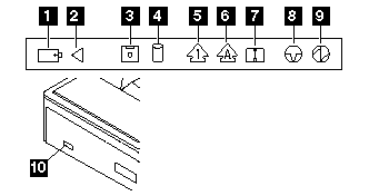
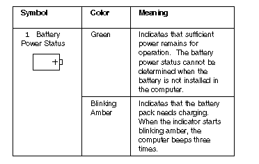
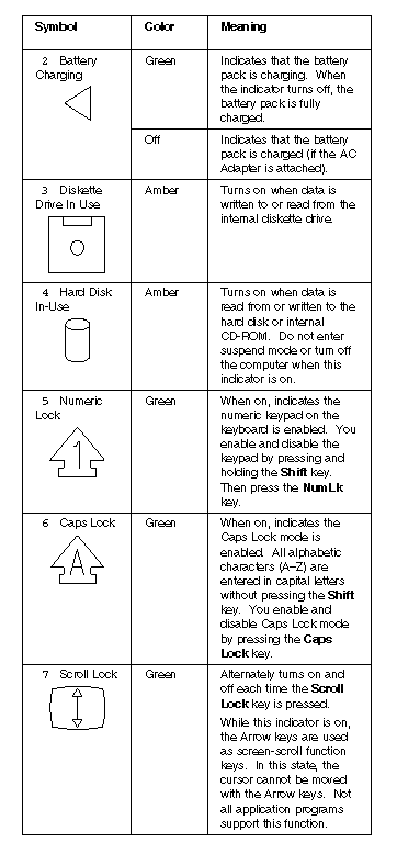
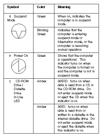
The system status LED indicators show the current computer status in green and amber using symbols. The following shows the location of each symbol and the meaning of each indicator.
Symbol Color Meaning:
How to Run the Diagnostics:
Use either the TrackPoint III or the cursor move keys to interact with the tests. The Enter key works the same as selecting the OK icon to reply OK.
|
Note: |
1. Press and hold the F1 key; then power on the computer. Hold the F1 key down until the Easy-Setup screen appears.
2. Select Test and press Enter.
3. Select a device and press Enter to run the test.
4. The test progress screen appears.
5. OK appears when the test ends without any errors.
6. Start the Advanced Diagnostic test by pressing Ctrl+A on the basic diagnostic menu screen.
7. Select Tool to install the tools.
8. Select a device, press the Spacebar and install the tool. Multiple devices can be selected by repeating this step.
A | mark appears beside the selected devices.
9. Select OK and press Enter if the selection is OK.
10. Select a device and press Enter to start the tests.
11. Select Test All to test all devices.
12. Select Loop Test to run the tests in a repeated loop.
A loop option menu appears in which a device loop or all-device loop can be selected. Select a device and press the Spacebar to select a device. Repeat this step to select multiple devices. Press Enter to start the diagnostic loop. If no device is selected, all device tests are looped.
13. To exit the loop, keep pressing Ctrl+ Pause until the test exits. A beep sounds to notify that the exit interrupt is sensed by the test program.
Error Log:
Diagnostic errors are printed on the printer that is attached to the parallel port when the error is detected. The error is also logged in the system memory.
Do the following to display the errors:
1. End the test, if it is running.
2. Press Ctrl+A to select the advanced diagnostic mode.
3. Press Ctrl+E.
4. The error log appears.
5. To exit the screen, select the cancel icon or press Esc.
The error log is not saved when the system is powered-off.
Diagnostic Error Codes:
If an error is detected, the following appears:
Large X on the left side of the device icon.
Device ID (three digit)
Error code (two digit)
FRU code (four digit)
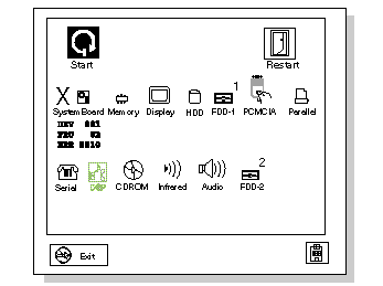
The device ID and error code are used to indicate the detail portion of the FRU which caused the error. If replacing a FRU does not correct the problem, see the device ID or error code from the previous failure. If they have changed, the cause might be because the new FRU is defective or that the FRU was incorrectly installed.
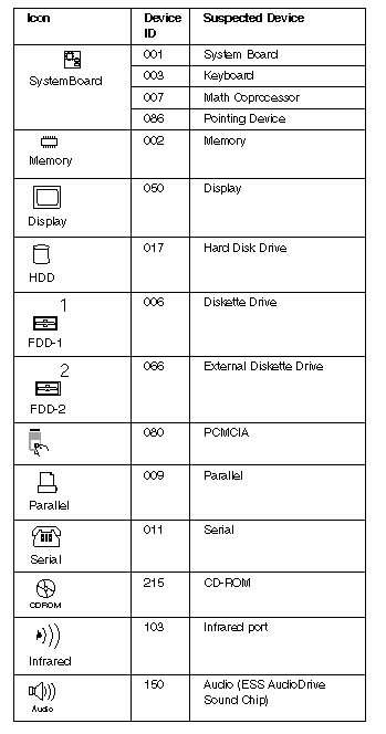
Device ID:
If an error is detected by the diagnostic tests, a three-digit device ID is displayed. The device ID indicates the suspected device.
FRU Codes:
If an error is detected by the diagnostic tests, a four-digit FRU code is displayed. The FRU code indicates two suspected FRUs. Replace the FRU that is indicated by the two leftmost digits first, then replace the FRU indicated by the two rightmost digits. No FRU is assigned to code 00. If only one FRU is suspected, the other FRU code is filled with zeros. See the referenced page before replacing the FRU.
|
FRU Code |
FRU/Action |
|
10 |
System Board |
|
11 |
CPU Card |
|
20 |
Memory |
|
30 |
Reserved |
|
32 |
External Keyboard |
|
33 |
External Mouse |
|
40 |
LCD Assembly |
|
45 |
External CRT |
|
50 |
1. Reseat the Diskette Drive (FDD-1) |
|
51 |
1. Reseat the Diskette Drive (FDD-2) |
|
60 |
1. Reseat the Hard Disk Drive (HDD) |
|
72 |
PCMCIA Slot Assembly |
|
90 |
CD-ROM Drive |
If the problem remains after replacement of the FRUs, go to ¿Undetermined Problems—.
Checking the Installed Devices List:
If a device is installed but the icon appears in a gray shade rather than a dark shade on the basic diagnostics screen, the device is defective. Reseat the device connectors. If the symptom remains, replace the device or the system board. If needed, adjust the contrast control to clearly distinguish the shade of the icon.
If a device that is not installed appears in a dark shade (for example, FDD-2 appears in a dark shade when no second FDD is installed), do the following:
1. Replace the first device in the configuration, such as the FDD-1.
2. If the problem remains, replace the system board.
The PCMCIA, Parallel, and Serial icons are always displayed in a dark shade because the icons represent subsystems of the system board and not the actual attachment of the devices.
The FDD-1 icon represents the first drive in the system configuration. Similarly, the FDD-2 icon represents the second drive,
attached to the external diskette drive connector or through a Port Replicator.
Password Combinations (POP, HDP, PAP):
When the power-on password (POP), hard disk password (HDP), and supervisor password (PAP) are used, the following situations may occur:
When the POP is the same as the HDP
- The POP prompt appears, but the HDP prompt does not appear.
When the POP is not the same as the HDP
- The POP and HDP prompts both appear.
When the PAP and HDP are enabled
- When a PAP is used, the HDP is enabled automatically, but no HDP prompt appears. The HDP is set to the same password as the PAP.
How to Run a Low-Level Format:
Do the following to format the hard disk.
|
Warning: |
1. Power off the computer.
2. Insert the ThinkPad 750Ce hardware maintenance diskette into diskette driveA and power on the computer.
Note:
You can use this maintenance diskette for the ThinkPad 365X and 365XD computers.
3. Select Format the hard disk from the main menu.
4. Select the drive from the menu.
5. Follow the instructions on the screen.
PC Test Card LED:
The green LED on the PC test card turns on when the PCMCIA test is running. If the LED does not turn on, check that the card is installed correctly by reseating the card. If it still does not turn on after it is reseated, try using another slot for the test. If the LED still does not turn on and the test fails, replace the FRU shown by the diagnostic error code.
Fn Key Combinations:
The following table shows the Fn key and function key combinations and their corresponding functions.
The Fn key works independently from the operating system. The operating system obtains the status through the system management interface to control the system.
|
Fn+ |
Description |
|
F1 |
Reserved |
|
F2 |
Fuel-Gauge display ON/OFF |
|
F3 |
Standby mode invocation |
|
F4 |
Suspend mode invocation |
|
F5 |
Reserved |
|
F6 |
Reserved |
|
F7 |
LCD/CRT display switching |
|
F8 |
Reserved |
|
F9 |
Reserved |
|
F10 |
Reserved |
|
F11 |
Power management mode switching |
|
F12 |
Hibernation invocation |
|
Page Up |
Reserved |
|
Page Down |
Reserved |
|
Search Keywords |
| |
|
Hint Category |
Hardware Maintenance Information | |
|
Date Created |
19-02-97 | |
|
Last Updated |
07-04-98 | |
|
Revision Date |
13-03-99 | |
|
Brand |
IBM ThinkPad | |
|
Product Family |
ThinkPad 365X/XD | |
|
Machine Type |
2625 | |
|
Model |
Various | |
|
TypeModel |
| |
|
Retain Tip (if applicable) |
| |
|
Reverse Doclinks |