
|
30.889 bytes |
Service Hints & Tips |
Document ID: GSMH-3BNJM3 |
|
This document is provided to IBM and our Business Partners to help sell and/or service IBM products. It is not to be distributed beyond that audience or used for any other purpose. |
TP 701C/CS - Related Service Procedure
Applicable to: World-Wide
Related Service Procedures:
Understanding Fn Key Combinations:
The following table shows the Fn key and function key combinations and their corresponding functions.
The Fn key works independently from the operating system. The operating system obtains the status through the system management interface to control the system.
|
Fn+ |
Description |
|
(alone) |
Resumes operation from Suspend mode. |
|
F1 |
Enters the Configuration Utility. |
|
F2 |
Turns the battery-gauge icon on and off. |
|
F3 |
Enters Standby mode. |
|
F4 |
Enters Suspend mode. |
|
F5 |
Mutes and unmutes speaker. |
|
F6 |
Turns the hard disk off. |
|
F7 |
Cycles through display options (LCD, CRT, both). |
|
F8 |
Reverses video display. |
|
F9 |
Reserved. |
|
F10 |
Reserved. |
|
F11 |
Reserved. |
|
F12 |
Enters Hibernate mode. |
|
Insert |
Increases contrast. |
|
Delete |
Decreases contrast. |
|
Home |
Increases brightness. |
|
End |
Decreases brightness. |
|
PgUp |
Increases speaker volume, unmutes speaker. |
|
PgDn |
Decreases speaker volume. |
Reading Status Indicators:
The system status indicators show the current computer status in different colors (green and yellow).
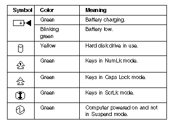
Reading the Battery Status:
If the computer. is using the battery, the Battery Status field in the Configuration utility. indicates whether the battery is OK or low. If the computer is using external power, this field indicates whether the battery is fully charged or still charging. The battery fuel gauge provides a visual indication of the battery power level.
Understanding the Power-On Self-Test:
Each time you power-on the computer, the power-on self-test (POST) is initiated. The POST takes up to 90 seconds to complete, depending on the options installed. The POST checks the following items: system boards, memory, display, keyboard, diskette drive, hard disk drive, parallel port, and serial port.
To start the POST, power-on the computer. The following actions will happen:
1. If a critical error occurs during the POST, the system halts. The system might beep or display a message.
If the POST cannot be completed successfully, an error code appears on the display, and you are prompted to press Esc or Enter. If you press Esc , the computer bypasses the error and attempts to complete the POST. If you press 28 Enter , the computer displays the Configuration Utility window. You can then try to correct the error. (See ┐Running the Diagnostics.Ś)
2. The computer issues one short beep when the POST ends successfully.
3. The computer attempts to load the operating system as customized. If the computer does not find an operating system, it displays a graphic message requesting that you insert a bootable diskette in the diskette drive and press F1 to resume operation.
Removing the Power-On Password:
To remove the power-on password, perform the following steps:
1. Power-off the computer.
2. Remove the SO-DIMM. door. For an illustration of the location of the SO-DIMM door.
3. Locate the two pads near the SO-DIMM. For an illustration of the pads, see ┐Bottom System Board (Bottom View)Ś.
4. Use a slim metal bar such asa paper clip to short the pads by placing the metal bar across the two pads.
5. Replace the SO-DIMM door.
6. Power-on the computer. and wait until the POST ends.
7. Verify that the password prompt does not appear.
The customer must set a new password to restore power-on password protection. The customer will also need to reset the former configuration in the configuration utility.
Running the Diagnostics.
Use either the Trackpoint III. or the cursor movement keys to interact with the tests. When asked for an ┐OKŚ response, press Enter or select the OK button.
1. With the computer powered-off, attach any test tools to the device to be tested. For example, attach a wrap plug to the serial port on the Multiport II or insert the PC test cards in the PCMCIA slot.
2. Power-on the computer. Press the F1 key any time while the POST memory count is proceeding. When the memory test is completed, the easy-setup screen appears.
3. Select Test and press Enter.
4. Press Ctrl+A to enter advanced diagnostics.
5. Select Tool to install a test tool.
Select the test tool for a device, and press the spacebar or click button to install it. A | mark appears for the selected device. Repeat this step to install multiple devices.
Note:
A graphic message prompts you to attach the selected test tools.
6. Select OK and press Enter if the selection is correct.
7. Select a device and press Enter to start the tests.
8. Select Test All to test all devices.
9. Select Loop test to loop tests.
A loop option menu appears in which you can select a loop test for one or more devices. Select a device and press the spacebar or click key.A | mark appears for the selected device. Repeat this step to select multiple devices. Press Enter to start the diagnostic loop. If no device is selected, all device tests are looped.
10. To exit the loop, keep pressing Ctrl+ Pause until the test exits. The system emits a beep sound to notify you that the test program has received the exit interrupt.
11. Press Esc to exit the test screen.
12. Choose Restart to leave easy-setup and restart your system.
13. Select OK or press Enter to confirm the restart.
Printing and Displaying Error Logs:
Diagnostics errors are printed on the printer that is attached to the parallel port when the error is detected. The error is also logged in the system memory.
Use the following procedure to display the errors:
1. End the test, if it is running.
2. Press Ctrl+A to enter the advanced diagnostics.
3. Press Ctrl+ E.
4. The error log appears.
5. To exit the screen, select Cancel or press Esc.
The error log is not saved when system power is turned off.
Checking Installed Devices:
Installed devices are displayed as dark icons on the diagnostics screen. All other devices are displayed with gray icons.
If a device is installed but the icon appears gray rather than dark, the device is defective. Reseat the device connectors, and then restart diagnostics. If the symptom remains, replace the device or the system board. If needed, adjust the contrast control to clearly distinguish the shades of the icon.
If a device that is not installed appears in a dark shade, for example, if HDD-2 appears in a dark shade when a second Hard Disk Drive is not installed, perform the following steps:
1. Replace the first device, such as HDD-1.
2. If the problem persists, replace the relevant system board.
The PCMCIA, System Board, Display, and infrared transreceiver icons are always displayed in a dark shade, because the icons represent subsystems of the system board and not attached devices. The parallel port icon is dark except when the diskette drive is attached to the parallel port; in that case, the FDD icon is dark and the parallel port icon is gray. Icons for devices attached through the Multiport II are dark when the devices are attached, and are gray when the devices are removed from the Multiport II.
The HDD-1 icon represents the first drive in the system configuration. Similarly, the HDD-2 icon represents the second drive, attached to the docking station.
Running the Low-Level Format:
Perform the following steps to format the hard disk:
Warning:
All data and formatting on the disk will be destroyed and cannot be recovered. Have the user make a backup copy of all information on the hard disk that should be saved. Make sure that a bootable diskette is available. Make sure that the drive address to be formatted is correct.
Use either the Trackpoint III or the cursor movement keys to interact with the tests. When asked for an ┐OKŚ response, press Enter or select the OK button.
1. Power-off the computer, and then power it on again.
2. Press the F1 key any time while the POST memory count is proceeding. When the memory test is completed, the easy-setup screen appears.
3. Select Test and press Enter.
4. Press Ctrl+A to enter advanced diagnostics.
5. Press Ctrl+F. The Format icon appears at the top of the advanced diagnostics screen.
6. Select the Format icon and press Enter.
7. Select the hard disk to be formatted and press Enter.
8. A confirmation screen appears, showing the number of cylinders, heads, and sectors on the hard disk.
9. Press Esc to exit the low-level format screen without formatting the hard disk.
10. Press Enter to begin the low-level format of the hard disk. When the low-level format is completed, the advanced diagnostic screen is displayed.
11. When you restart the computer, a graphic message is displayed at the end of POST, requesting that you insert a bootable diskette into the diskette drive and press F1 to resume operation.
Reading the PC Test Card LED:
The green LED on a PC test card (JEIDA/PCMCIA wrap card) turns on when the PCMCIA test is running. If the LED does not turn on, check that the card is installed correctly by reseating the card. If it still does not turn on after the card is reseated and you are using one PC test card, try using the other slot for the test. If you are using two cards, try swapping the cards in the slots. If the LED still does not turn on and the test fails, replace the FRU shown in the diagnostics error code.
Removing PCMCIA Cards:
After removing the PCMCIA cover, and filler plug if it is installed, you can insert or remove PCMCIA cards during most computer operations.
To insert a PCMCIA card, perform the following steps:
1. Insert the PCMCIA card into one of the available slots, with the long row of pin sockets facing the computer and the label on the PCMCIA card facing up. When the card is in place, the blue eject button at the left of the slot pops out. Do not force the card. If the card does not fit into the slot, turn it over.
Note:
A Type III PCMCIA card occupies both PCMCIA slots. To insert the card, aim its bottom ridges at the lower PCMCIA card slot.
2. Replace the outer cover over the PCMCIA slots.
To remove a PCMCIA card, perform the following steps:
1. Use a small pointed object such as the point of a pen to press the blue eject button located to the left of the PCMCIA card slot.
Note:
A Type III PCMCIA card occupies both PCMCIA slots. To remove the card, press the bottom eject button.
2. Carefully slide the PCMCIA card out of the slot.
3. If both PCMCIA slots are empty, replace the filler plug and replace the outer cover over the PCMCIA slots.
Note:
Do not remove PCMCIA cards while the system is in Suspend or Hibernate mode. If you remove a PCMCIA card while the system is in either mode, you might lose configuration information. Or, if you remove a PCMCIA card and insert another card, your system might not recognize the new card.
|
Search Keywords |
| |
|
Hint Category |
Hardware Maintenance Information | |
|
Date Created |
22-11-96 | |
|
Last Updated |
01-05-98 | |
|
Revision Date |
27-04-99 | |
|
Brand |
IBM ThinkPad | |
|
Product Family |
ThinkPad 701 | |
|
Machine Type |
2630 | |
|
Model |
Various | |
|
TypeModel |
| |
|
Retain Tip (if applicable) |
N/A | |
|
Reverse Doclinks |