

|
723.026 bytes |
Service Hints & Tips |
Document ID: GSMH-3DAFKY |
TP Dock 1 - FRU Removals and Replacements
Applicable to: World-Wide
FRU Removals and Replacements:
This section contains information on removals and replacements, and locations.
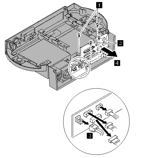
The arrows in the removals and replacements show the direction of movement to remove a field replaceable unit (FRU), or to turn a screw to release the FRU. The arrows are marked in numeric order to show the correct sequence of removal. When other FRUs must be removed before removing the failing FRU, they are listed at the top of the page. Go to the removal procedure for each FRU listed, remove the FRU, and then continue with the removal of the failing FRU.
To replace a FRU, reverse the removal procedure and follow any notes that pertain to replacement. See 'Locations— for internal cable connections and arrangement information.
CAUTION:
Before removing any FRU, power-off the Dock I, remove the computer, unplug all power cords from electrical outlets, then disconnect any interconnecting cables.
CAUTION:
In the U.K., by law, the telephone cable must be connected after or disconnected before the power cord.
Warning:
The main board, adapters, and circuit boards on the drives are sensitive to, and can be damaged by, electrostatic discharge. Establish personal grounding by touching a ground point with one hand before touching these units.
Note:
An electrostatic discharge (ESD) strap must be used to establish personal grounding.
Important:
See the - 'Screw Size Chart' - to match the letters to the correct screw type and size before replacing each screw.
1010 Bottom Cover:
|
1 |
2 |
3 |
1020 Video Cable Cover:
|
1 |
2 |
3 |
4 |
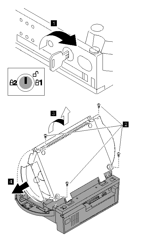
|
Step |
Color and type |
Length |
|
2 |
Black screw (4) |
7 mm (0.28 in.) |
1030 Blank Bezel:
Bottom Cover (1010)
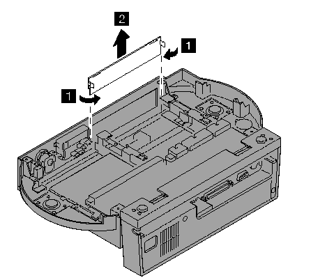
Note:
When you install the blank bezel, set the edge of the bezel into the groove of the Dock I. Then put the latch of the bezel into the Dock I catch.
1040 LED Assembly:
Bottom Cover (1010)
|
1 |
2 |
3 |
Note:
When you install the LED assembly in the Dock I:
1. Put the edge of the LED assembly into the groove.
2. Put the status indicators and headphone jack into the each hole.
3. Hook the (4) to the guide.
4. Reinstall the two screws.
1050 Buzzer:
Bottom Cover (1010)
|
5 |
6 |
7 |
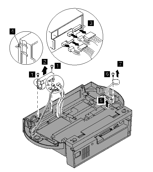
|
Step |
Color and type (quantity) |
Length |
|
1 |
White self tapping for plastics (2) |
8 mm (0.31 in.) |
|
6 |
White screw (1) |
5 mm (0.20 in.) |
Note:
Make sure you use the correct screw.
1060 Key Lock Assembly:
Bottom Cover (1010)
|
1 |
2 |
3 |
4 |
5 |
1070 Security Feature:
Bottom Cover (1010)
LED Assembly (1040)
Open the release/lock lever of the Dock I by setting the key to the center position  and moving the slide-knob to the right.
|
1 |
2 |
3 |
4 |
5 |
6 |
7 |
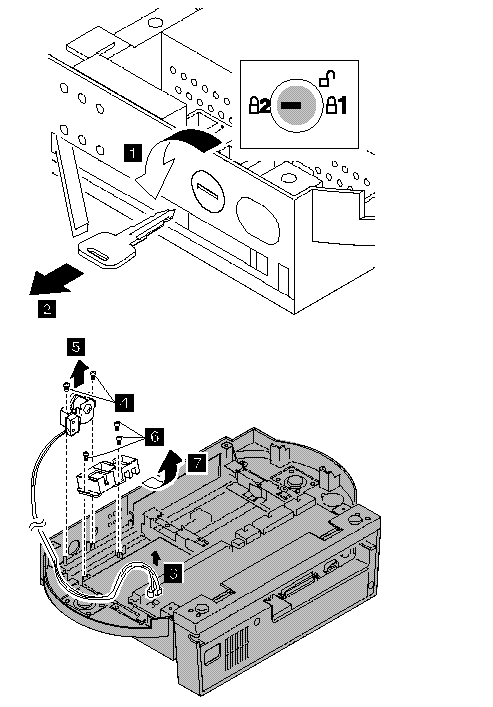
|
Step |
Color, type, quantity |
Length |
|
4 |
Black self tap screw (2) |
8 mm (0.31 in.) |
|
6 |
White self tap screw (3) |
5 mm (0.20 in.) |
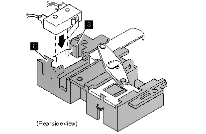
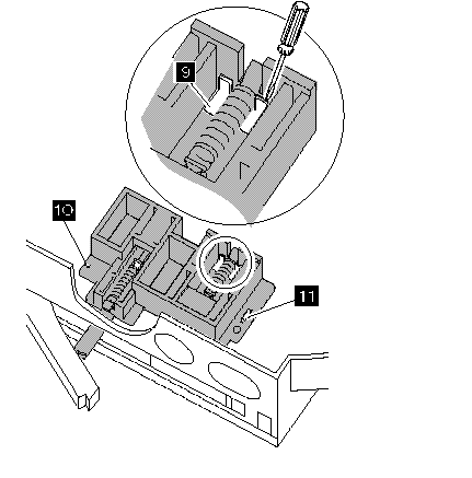
To install the Dock I security feature, do the following.
1. Fasten the microswitch with the latchesÌ8Ï.
2. Assemble the three highlighted parts as shown.
3. Set 9, 10 , andÌ 11 of the Dock I into the security feature as shown.
4. Reinstall the three screws.
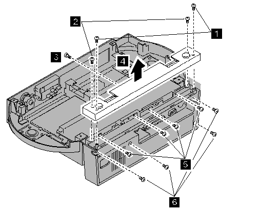
1080 Main Board:
Bottom Cover (1010)
|
Step |
Color and type (quantity) |
Length |
|
1 |
Black self tap screw (2) |
8 mm (0.31 in.) |
|
2 |
Black screw (2) |
5 mm (0.20 in.) |
|
3 |
White screw (1) |
5 mm (0.20 in.) |
|
5 |
White screw (4) |
5 mm (0.20 in.) |
|
6 |
Black screw (4) |
5 mm (0.20 in.) |
Note:
Make sure you use the correct screw.
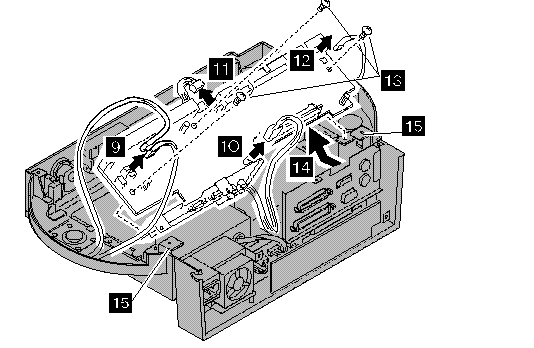
|
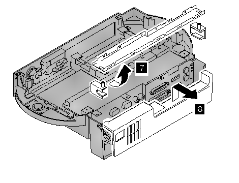
9 |
Disconnect the three connectors. |
|
10 |
Disconnect the audio card interface connector. |
|
11 |
Disconnect the power supply connector P1. |
|
12 |
Disconnect the buzzer connector. |
|
13 |
Remove the three screws. |
|
14 |
Disconnect the I/O card interface connector and remove the main board. Warning: |
|
Step |
Color and type (quantity) |
Length |
|
13 |
White screw (3) |
5 mm (0.20 in.) |
Note:
Make sure you use the correct screw.
1090 Speaker:
Bottom Cover (1010)
Main Board (1080)
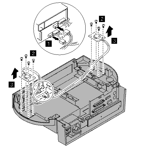
|
Step |
Color and type (quantity) |
Length |
|
2 |
White self tap screw (8) |
6 mm (0.24 in.) |
Note:
Make sure you use the correct screw.
1100 Audio Card:
Bottom Cover (1010)
Main Board (1080)
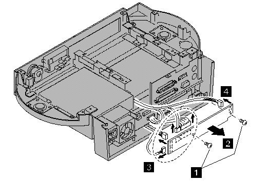
Note:
3 When you remove the four connectors, note the location of each connector.
|
Step |
Color and type (quantity) |
Length |
|
1 |
White screw (2) |
5 mm (0.20 in.) |
Note:
Make sure you use the correct screw.
1110 Power Supply Unit:
Bottom Cover (1010)
Main Board (1080)
Open the release/lock lever

Warning:
When doing sequence 5 , remove the audio card only enough to disconnect the power supply connecters under the card.
Do not pull the card out because there are three more cables connected to the card.
|
Step |
Color and type (quantity) |
Length |
|
1 |
White screw (6) |
5 mm (0.20 in.) |
|
2 |
Black self tap screw (1) |
8 mm (0.31 in.) |
|
4 |
White screw (2) |
5 mm (0.20 in.) |
Note:
Make sure you use the correct screw.
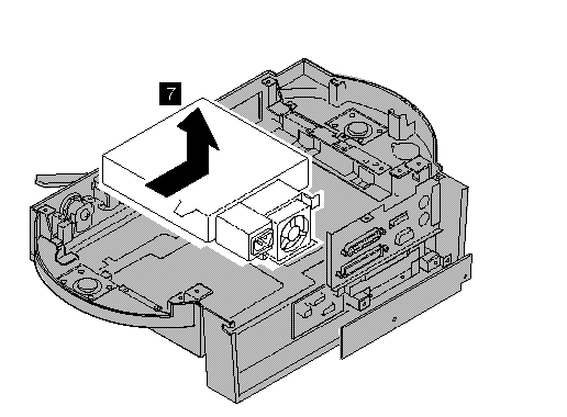
1120 I/O Card:
Bottom Cover (1010)
Main Board (1080)
Audio Card (1100)
|
Step |
Color and type (quantity) |
Length |
|
1 |
White screw (2) |
5 mm (0.20 in.) |
|
2 |
White self tap screw (2) |
5 mm (0.20 in.) |
Note:
Make sure you use the correct screw.
|
Search Keywords |
| |
|
Hint Category |
Hardware Maintenance Information | |
|
Date Created |
13-01-97 | |
|
Last Updated |
27-08-98 | |
|
Revision Date |
21-08-99 | |
|
Brand |
IBM ThinkPad | |
|
Product Family |
ThinkPad Docking Stations | |
|
Machine Type |
3545 | |
|
Model |
001 | |
|
TypeModel |
| |
|
Retain Tip (if applicable) |
N/A | |
|
Reverse Doclinks |