|
38.396 bytes |
Product Information |
Document ID: MCGN-46BRE6 |
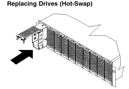
Netfinity EXP15 - Replacing drives (Hot Swap)
Applicable to: World-Wide
Source: Hardware Maintenance Manual

To remove the hot-swap drives:
1. Pull on the bottom of the tray lever to release the lever.
2. Lift the lever and slide the drive partially out of the slot.
|
Note
Wait at least 20 seconds before fully removing the drive from the Expansion Unit to allow for spin down. Allowing for spin down
avoids possible damage to the drive.
See "Drive Numbering" when replacing drives. |
3. Install the new drive, Making sure at least ten seconds have passed before you install the new drive tray. Unlatch and open the drive lever and insert the
drive.
4. Lock the lever in place.
5. Check the LEDs.
a. When drives are ready for use, the green Active LEDs should be off and the Power/Fault LEDS should be glowing green. (A flashing amber LED indicates a drive rebuild).
b. If the Power/Fault light is solid amber, pull up on the drive latch and lift the drive lever to pull the drive partially out of the bay. Wait at least 20 seconds before fully removing the drive from the Expansion Unit to allow for spin down. If the SCSI adapter is the IBM ServeRAID; go to the ServeRAID User's Guide for additional information and procedures on changing the state of the drive from the current Default state to any other state (for example, HSP, RDY, rebuild drive to ONL, and so on). The amber LED should go off within 10 seconds of the drive state change (to something other than DDD).
If the SCSI adapter is the IBM ServeRAID II, in some cases, the drive will automatically reset to either a hotspare (HSP) or be rebuilt (ONL). See the ServeRAID II User's Guide for additional information. If the state change in the ServeRAID II configuration does not change automatically (amber LED does not go off), then refer to the ServeRAID II User's Guide for directions on how to perform a manual drive state change. The amber LED should go off within 10 seconds of a drive state change (to something other than DDD).
If the state change in the RAID configuration does not change automatically, refer to the RAID Controller User's Guide for directions on how to perform a drive state change.
LED drives status:
The following table shows the LED status on the drives:
|
LED |
Description |
|
Activity (green) |
Indicates read/write or inquiry operation |
|
Power/Fault (green) |
Indicates drive present |
|
Power/Fault (amber/green Flashing) |
Indicates drive rebuild |
|
Power/Fault (amber) |
Indicates a drive failure |
|
|
Search Keywords |
|
|
Document Category |
Diagrams |
|
|
Date Created |
25-03-99 |
|
|
Last Updated |
21-05-99 |
|
|
Revision Date |
|
|
Brand |
IBM PC Server |
|
Product Family |
Rack/Storage Enclosures |
|
|
Machine Type |
3520 |
|
|
Model |
ALL |
|
|
TypeModel |
|
|
|
Retain Tip (if applicable) |
|
|
|
Reverse Doclinks
and Admin Purposes |
|


