
|
68.416 bytes |
Service Hints & Tips |
Document ID: BMOE-42JJUW |
TP 560Z - Checkout Guide
Applicable to: World-Wide
The following information is intended for IBM Dealers and Authorized Servicers only. Customers attempting to follow any of the procedures below may void their warranty.
Checkout Guide
Use the following procedure as a guide for computer problems.
Note: The diagnostic tests are intended to test only IBM products. Non-IBM products, prototype cards, or modified options can give false errors and invalid system responses.
1. Obtain the failing symptoms in as much detail as possible.
2. Verify the symptoms by attempting to re-create the failure by running the diagnostic test or by repeating the same operation.
Note: To run the diagnostics, refer to "Running the Diagnostics"
3. Use the following table with the verified symptom to determine which page to go to. Search the symptoms column, and find the description that best matches your symptom; then go to the page shown in the "Go To" column.
|
Symptoms (Verified) |
Go To |
|
Power failure (The power indicator does not go on or stay on). |
"Power Systems Checkout" |
|
POST does not complete. No beep or error codes are indicated. |
"Symptom-to-FRU Index" and then use the No Beep Symptoms table. |
|
POST beeps, but no error codes are displayed. |
"Symptom-to-FRU Index", and then use the Beep Symptoms table. |
|
POST detected an error and displayed numeric error codes. |
"Symptom-to-FRU Index", and then use the Numeric Error Codes table. |
|
The diagnostic test detected an error and displayed a FRU code. |
"Running the Diagnostics" |
|
The configuration is not the same as the installed devices. |
"Checking the Installed Devices List" |
|
Other symptoms (such as LCD display problems). |
"Symptom-to-FRU Index", and |
|
Symptoms cannot be re-created (Intermittent problems). |
Use the customer-reported symptoms and go to "Symptom-to-FRU Index". |
2. Click on Exit twice.
3. Click on FDD-1 or FDD-2 to start the test.
4. Insert the blank diskette when instructed and follow the instructions on the screen.
5. If the controller test detects an error, FRU code 10 appears. Replace the system board.
6. If the controller test runs without errors, the drive read/write tests start automatically. If a drive test detects an error, FRU code 50 for FDD-1 or 51 for FDD-2 appears. If the diskette itself is known to be good, replace the drive.
7. If the FDD-2 test detects an error, move the drive to the computer's diskette drive connector directly, if possible, and test it again as FDD-1.
If no errors occur in the FDD-1 position, the drive is not defective. Go to "Port Replicator Checkout" to isolate the port replicator problem.
Keyboard or Auxiliary Input Device Checkout
If the internal keyboard does not work or an unexpected character appears, make sure that the flexible keyboard cable is firmly connected to the system board. If it is firmly connected, then run the Keyboard Test. If an external keyboard is connected, remove it before running the Keyboard Test for the internal keyboard. See "Running the Diagnostics" for details.
Note: When the Fn key is pressed, a black square briefly appears.
If the Keyboard Test detects a keyboard problem, do the following one at a time to correct the problem. Do not replace a nondefective FRU:
Replace the flexible keyboard cable.
Replace the keyboard.
Replace the system board.
The following auxiliary input devices are supported for this computer:
Numeric keypad
Mouse (PS/2 compatible)
External keyboard (with keyboard/mouse cable)
If any of these devices do not work, reseat the cable connector and repeat the failing operation.
If the problem does not recur, the problem may have been in the connector. Recheck the connector.
If the problem is not corrected, replace the device and then the system board.
Memory Checkout
EDO DIMM cards are available for increasing the memory capacity.
|
DIMM |
Displayed Value |
Displayed Value |
|
No DIMM card |
32192 KB |
64960 KB |
|
8 MB (not supported |
40384 KB |
73152 KB |
|
16 MB |
48576 KB |
81344 KB |
|
32 MB |
64960 KB |
97728 KB |
|
64 MB |
97728 KB |
130496 KB |
Use the following procedure to isolate memory problems.
Note: Make sure that the DIMM card is fully installed into the connector. A loose connection can cause an error.
See "Running the Diagnostics" for details.
1. Power off the computer and remove the DIMM card from its slot (if installed).
2. Press and hold the F1 key; then power on the computer. Hold the F1 key down until the Easy-Setup menu appears.
3. Select Test and press Enter.
4. Select Memory and press Enter to run the memory test on base memory. If an error appears, replace the system board.
5. Power off the computer and reinstall the DIMM card; then power on the computer. Verify the memory size; then test the memory. If an error appears, replace the DIMM card.
If memory problems occur, use the loop option to repeat the test. If the test detects an error, an error log will be printed on the printer connected to the parallel port. See "Displaying the Error Log" for more information.
Flash Memory Update:
System setup programs and diagnostic tests are stored in the flash memory. The flash memory update is required for the following conditions:
New versions of system programs
New features or options
To update the flash memory, do the following:
1. Get the appropriate diskette containing the update.
2. Insert the System Program Service Diskette into drive A and power on the computer.
3. Select Update system programs from the menu.
Fan Checkout
To check the fan, do the following:
1. Start Easy-Setup.
2. Click on Test. The fan will start so you can check the air turbulance at the fan louver.
3. Press Ctrl + A to enter the advanced diagnostic mode. The ThinkPad FRU Connections window appears. If the fan connector is not connected, the
Fan not connected message appears.
4. Click on Exit. The keyboard layout appears on the screen.
5. Click on Exit again.
6. Click on System Board then press Enter to run the test.
Follow the description in the window. If the test detects a fan problem, replace it.
Port Replicator Checkout
Use the following procedure to isolate a port replicator problem. The port replicator attaches to the system expansion connector at the bottom of the computer.
1. Power off the computer.
2. Remove the failing devices from the port replicator.
3. Unplug the AC adapter from the port replicator, if attached.
4. Remove the port replicator from the computer.
5. Reconnect the failing device directly to the computer. (If another device is already connected to the computer, remove it first.)
6. Go to the "Running the Diagnostics" and run the diagnostics.
7. If the advanced diagnostic device test did not find an error, suspect a problem with the port replicator of the system expansion bus.
8. Power off the computer and reconnect the port replicator.
9. Power on the computer and run the following advanced diagnostic tests:
1. Remove the battery pack and the diskette drive.
2. Connect the AC Adapter and check that power is supplied.
3. Disconnect the AC Adapter and install the charged battery pack; then check that power is supplied by the battery pack. If you suspect a power problem, see the appropriate power supply checkout in the following list:


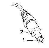
If the voltage is not good, replace the AC Adapter.
If the voltage is within the range, do the following:
Replace the system board.
If the problem is not corrected, go to "Undetermined Problems".
Note: An audible noise from the AC Adapter does not always indicate a defect.
Checking Operational Charging:
To check operational charging, use a discharged battery pack or a battery pack that has less than 50% of the total power remaining when installed in the computer.
Perform operational charging. If the battery status indicator does not turn on, remove the battery pack and let it return to room temperature. Reinstall the battery pack.
If the charge indicator still does not turn on, replace the battery pack.
If the charge indicator still does not turn on, replace the system board. Then reinstall the battery pack.
If the reinstalled battery pack is not charged, go to the next section.
Checking the Battery Pack:
Battery charging will not start until the Fuel-Gauge shows that less than 95% of the total power remains; with this condition the battery pack will charge to 100% of its capacity. This protects the battery pack from being overcharged or having a shortened life.
Do the following:
1. Power off the computer.
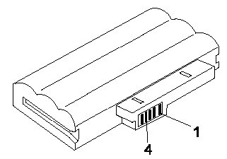
2. Remove the battery pack and measure the voltage between battery terminals 1 (+) and 4 (N). See the following figure:

3. If the voltage is less than +11.0 V dc, the battery pack has been discharged. Recharge the battery pack.
Note: In this case, the battery pack is over-discharged. It takes the at least 2 hours to recharge the battery pack even if the indicator does not turn on.
If the voltage is still less than +11.0 V dc after recharging, replace the battery pack.
4. If the voltage is more than +11.0 V dc, measure the resistance between battery pack terminals 3 and 4. The resistance must be 4 to 30 K ohm. If the resistance is not correct, replace the battery pack. If the resistance is correct, replace the system board.
Checking the Backup Battery
1. Power off the computer and unplug the AC Adapter from the computer.
2. Turn the computer upside down.
3. Remove the backup battery (see "1010 Backup Battery").
4. Measure the voltage of the backup battery. See the following figure.
Note: Be careful not to measure the wrong side of the backup battery.

If the voltage is correct, replace the system board.
If the voltage is not correct, replace the backup battery.
If the backup battery discharges quickly after replacement, replace the system board.
Status Indicator Checkout
If an LED problem occurs, do the following:
1. Power off the computer.
2. Power on the computer.
3. All the LEDs in the indicator panel, except the Hard Disk In Use LED, should turn on for a moment soon after the computer is powered on. Make sure they turn on.
If the problems persists, replace the system board.
System Board and CPU Mini-CartridgeCheckout
The system board and the CPU mini-cartridge FRUs perform the operation on the computer. Processor problems can be caused by either FRU. Generally, the CPU mini-cartridge has a lower failure rate. If a numeric code indicates the system board or the CPU mini-cartridge as failing, do the following procedure to isolate the problem:
1. Run the system board test to verify the symptom.
This test verifies both the system board and the CPU mini-cartrige. If no error is detected, return to "Undetermined Problems".
Note: Do not touch the keyboard and the pointing device when the system board is being tested. This might cause unexpected errors.
2. If FRU code 10 appears, replace the system board, but do not replace the CPU mini-cartrige. Transfer the CPU mini-cartrige from the old system board to the new system board.
3. If FRU code 11 appears, reseat the CPU mini-cartridge.
4. Rerun the test to verify the fix.
5. If FRU code 11 remains, replace the CPU mini-cartridge.
If this procedure does not correct the problem, go to "Undetermined Problems".
TrackPoint Checkout
If the TrackPoint does not work, do the following:
1. Run the ThinkPad Configurations program and check if the TrackPoint is enabled.
2. If it is not, select Enable and enable it.
3. If you still have a problem, continue to the next step.

4. Go to the Easy-Setup menu.
5. Move to an item with the TrackPoint.
6. Press either the left or the right click button.
7. Verify that both buttons work correctly.
8. Move to another item with the TrackPoint.
9. Press the TrackPoint. (Press-to-Select).
10. Verify that the item is selected.
11. If the problem still persists, do the following one at a time:
Warning: Do not replace a nondefective FRU.
Reseat the TrackPoint cable.
Replace the keyboard.
Replace the system board.
|
Search Keywords |
| |
|
Hint Category |
Hardware Maintenance Information | |
|
Date Created |
24-11-98 | |
|
Last Updated |
19-01-99 | |
|
Revision Date |
19-01-2000 | |
|
Brand |
IBM ThinkPad | |
|
Product Family |
ThinkPad 560Z | |
|
Machine Type |
2640, 2641 | |
|
Model |
Various | |
|
TypeModel |
| |
|
Retain Tip (if applicable) |
| |
|
Reverse Doclinks |