
|
44.623 bytes |
Service Hints & Tips |
Document ID: DDSE-3U6MRY |
PC Server 520 - System board location / jumper settings (8641-MZ0)
Applicable to: World-Wide
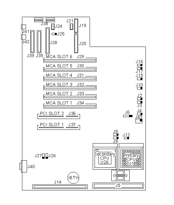
System Board Locations

Note:
A black square () indicates pin 1.
System Board Connections
|
Header |
Configuration |
Connect To |
|
J2 |
SCSI LED connector |
Yellow SCSI LED |
|
J3 |
IDE Hard Drive connector |
IDE hard drive |
|
J4 |
System Fan connector |
System fan |
|
J5 |
Cache Card Slot |
Cache Card |
|
J6 |
Speaker connector |
Speaker |
|
J8 |
Primary CPU Fan connector |
Fan |
|
J9 |
Secondary CPU Fan connector |
Fan |
|
J10 |
Power LED connector |
Pins 1-3 |
|
J13 |
IDE Hard Drive connector |
IDE hard drive |
|
J19 |
Parallel Port connector |
Parallel device |
|
J20 |
Diskette Drive connector |
Diskette drive |
|
J21 |
Serial Port COM 'B' connector |
Serial device |
|
J24 |
Serial Port COM 'A' connector |
Serial device |
|
J28 |
SCSI Standard connector |
SCSI device |
|
J35 |
SCSI Fast/Wide internal connector |
Internal SCSI Fast/Wide device |
|
J38 |
Power supply connector |
P1 and P2 |
|
J39 |
SCSI Fast/Wide external connector |
External SCSI Fast/Wide |
|
J40 |
Video connector |
Video |
|
J41 |
Keyboard connector |
Keyboard |
|
J42 |
Mouse connector |
Mouse |
System Board Jumpers
|
Jumpers |
Description |
Setting |
|
J12 |
Spare Jumper |
Parked = Pin 1 only Default |
|
J15 |
Password Write |
Disabled = Pins 1-2 Enabled = Pins 2-3 Default |
|
J16 |
C2 Cover Open | |
|
J17 |
C2 Key Lock | |
|
J25 |
Reset switch | |
|
J26 |
SCSI Select |
System Board = Pins 1-2 Default |
|
J27 |
Video Select |
System Board = Pins 1-2 Default |
|
J43 |
Clock Select |
60MHz = Pins 1-2 |
|
Search Keywords |
| |
|
Hint Category |
Hardware Maintenance Information, Processors | |
|
Date Created |
23-08-96 | |
|
Last Updated |
02-03-99 | |
|
Revision Date |
02-03-2000 | |
|
Brand |
IBM PC Server | |
|
Product Family |
PC Server 520 | |
|
Machine Type |
8641 | |
|
Model |
MZ0 | |
|
TypeModel |
| |
|
Retain Tip (if applicable) |
| |
|
Reverse Doclinks |