
|
51.817 bytes |
Service Hints & Tips |
Document ID: GSMH-3FHDNU |
IBM PC360 - Pentium Pro 150/200 MHz system board
Applicable to: World-Wide
PC 360-S150 (Type 6598) - Pentium Pro 150/200 MHz System Board:

Also see ¨Matrox Graphics Adapter (MGA) Switch Settings´ for MGA video adapter locations and switch settings.
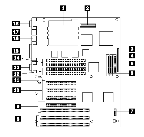
PC 360-S150 (Type 6598) - Pentium Pro 150/200 MHz System Board Locations:
|
1 |
Processor connector |
|
2 |
Power supply connector |
|
3 |
Front panel I/O connector |
|
4 |
Diskette drive connector |
|
5 |
Hard Disk Drive connector |
|
6 |
CD-ROM drive connector |
|
7 |
Configuration jumpers (J25) |
|
8 |
ISA adapter slots |
|
9 |
PCI/ISA adapter slots |
|
10 |
PCI adapter slots |
|
11 |
Backup battery |
|
12 |
Bank 0 memory connectors |
|
13 |
Serial port 2 |
|
14 |
Bank 1 memory connectors |
|
15 |
Parallel port |
|
16 |
Mouse port |
|
17 |
Keyboard port |
|
18 |
Serial port 1 |
See ¨PC 360-S150 (Type 6598) - Pentium Pro 150/200 MHz Jumper Settings´ and ¨PC 360-S150 (Type 6598) - Pentium Pro 150/200 MHz Jumper Setting Procedures´ for jumper settings and procedures.
PC 360-S150 (Type 6598) - Pentium Pro 150/200 MHz Jumper Settings:
See ¨PC 360-S150 (Type 6598) - Pentium Pro 150/200 MHz Jumper Setting Procedures´ for additional jumper
procedure information.
|
Attention:
|
The following table contains the jumper setting information. (D) indicates the default setting.
|
Jumper |
Setting |
Description |
|
Bus Speed |
1-2 |
150 MHz Processor |
|
Bus Speed |
2-3 |
200 MHz Processor |
|
Password |
14-15 (D) |
Password Enabled |
|
CMOS |
17-18 (D) |
CMOS Normal |
|
Setup Utility |
20-21 (D) |
Setup Enabled |
|
Flash Recovery |
23-24 (D) |
Normal |
|
Reserved |
26-27 (D) |
(Do Not Change) |
PC 360-S150 (Type 6598) - Pentium Pro 150/200 MHz Jumper Setting Procedures:
Processor/Bus-Speed/Clock-Ratio Jumper
Set these jumpers to match the processor installed.
Password Reset:
1. Power-off the computer.
2. Move the jumper from pins 14-15 to 13-14.
3. Power-on the computer. This erases both the power-on and administrator passwords.
4. Power-off the computer.
5. Move the jumper from pins 13-14 to 14-15.
CMOS Jumper:
1. Power-off the computer.
2. Move the jumper from pins 17-18 to 16-17.
3. Power-on the computer. This erases the CMOS information.
4. Power-off the computer.
5. Move the jumper from pins 16-17 to 17-18.
Configuration/Setup Utility Jumper:
This jumper setting enables and disables the Configuration/Setup Utility.
Flash Recovery Jumper:
If an interruption occurs during a Flash/BIOS upgrade, the BIOS might be left in an unusable state. This jumper enables you to restart the system and recover the BIOS.
1. Power-off the computer.
2. Move the jumper from pins 23-24 to 22-23.
3. Insert the upgrade diskette into the drive A.
4. Power-on the computer and listen to the speaker. You should hear beeps in the following sequence.
a. After the computer is powered-on, it beeps once. This beep marks the beginning of the POST.
b. After a short delay (less than 10 seconds), the computer beeps again. This marks the beginning of the recovery process. The recovery code is being copied into the flash component.
c. After about 30 seconds, the computer beeps twice, marking the end of the recovery process. Wait until the diskette drive in-use light goes out.
5. Power-off the computer and move the jumper from pins 22-23 to 23-24.
6. Leave the upgrade diskette in the diskette drive and power-on the computer.
7. Retry the original upgrade procedure.
|
Search Keywords |
| |
|
Hint Category |
Hardware Maintenance Information | |
|
Date Created |
25-03-97 | |
|
Last Updated |
30-04-98 | |
|
Revision Date |
24-04-99 | |
|
Brand |
IBM PC | |
|
Product Family |
PC 360 | |
|
Machine Type |
6598 | |
|
Model |
all | |
|
TypeModel |
| |
|
Retain Tip (if applicable) |
| |
|
Reverse Doclinks |