
|
25.855 bytes |
Product Information |
Document ID: MCGN-437P3G |
Netfinity 5500 M10 - SCSI Backplane component locations and SCSI Backplane option jumpers
Applicable to: World-Wide
SCSI Backplane Component Locations
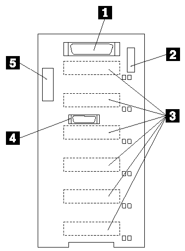
The following simplified layout of the SCSI backplane identifies the components. Refer to this figure when you set the jumpers on the backplane.

1 Wide (16-bit) SCSI connector
2 Option jumper block (J10)
3 SCSI hot-swap drive connectors (on reverse side of backplane)
4 Repeater card connector
5 Power connector
SCSI Backplane Option Jumpers
The option jumper block on the SCSI backplane defines the SCSI IDs for hot-swap drives. See the illustration in "SCSI Backplane Component Locations" for the location of the option jumper block.
Table 10 summarizes the settings for the SCSI backplane option jumper block (J10).
Table 10. Backplane Option Jumper Block
|
Pins |
Description |
|
1-2 |
Reserved. |
|
3-4 |
Reserved. |
|
5-6 |
Placing a jumper on these two pins enables SCSI IDs 8-13 |
|
7-8 |
Reserved. |
|
9-10 |
Reserved. |
|
11-12 |
Placing a jumper on these two pins reverses the SCSI IDs on the backplane. |
Table 11 shows the SCSI IDs that you can use for hot-swap drives.
Table 11. SCSI IDs for Hot-Swap Drives
|
J10 |
J10 |
Bay 1 |
Bay 2 |
Bay 3 |
Bay 4 |
Bay 5 |
Bay 6 |
|
No jumper |
No jumper |
0 |
1 |
2 |
3 |
4 |
5 |
|
No jumper |
Jumper |
5 |
4 |
3 |
2 |
1 |
0 |
|
Jumper |
No jumper |
13 |
12 |
11 |
10 |
9 |
8 |
|
Search Keywords |
| |
|
Document Category |
Diagrams | |
|
Date Created |
15-12-98 | |
|
Last Updated |
15-12-98 | |
|
Revision Date |
15-12-99 | |
|
Brand |
IBM PC Server | |
|
Product Family |
Netfinity 5500 M10 | |
|
Machine Type |
8661 | |
|
Model |
| |
|
TypeModel |
| |
|
Retain Tip (if applicable) |
| |
|
Reverse Doclinks |