
|
18.551 bytes |
Service Hints & Tips |
Document ID: DDSE-3QNJ7Q |
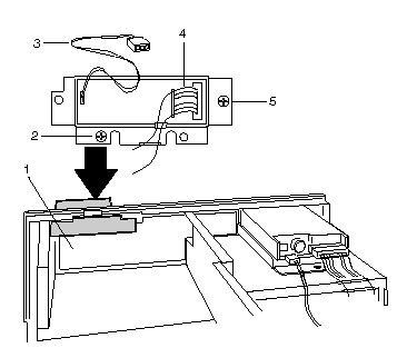
PCServer704 - Liquid Crystal Display diagram
Applicable to: World-Wide
Liquid Crystal Display

Diagram
1. Front panel control board
2. Two screws on LCD carrier
3. Backlight power connector from LCD to control boar
4. Signal connector from LCD to control board
5. Mounting Screw
Instructions
1. Remove screws that secure the liquid crystal display (LCD) to the chasis.
2. From inside the chasis, pull the carrier back out of opening.
3. To remove the LCD form the carrier, pry out the four plastic riveys.
4. Put the replacement LCD on the carrier, and secure the carrier with four plastic rivets.
5. From inside the chasis, place the carrier assembly back in the chasis opening. Make sure the carrier flanges make good contact with the chasis around the opening. (You may need to spread the flanges out a little.)
6. Reinstall the two screws to secure the carrier to the chasis.
|
Search Keywords |
| |
|
Hint Category |
Hardware Maintenance Information | |
|
Date Created |
19-06-96 | |
|
Last Updated |
20-05-98 | |
|
Revision Date |
19-05-99 | |
|
Brand |
IBM PC Server | |
|
Product Family |
PC Server 704 | |
|
Machine Type |
8650 | |
|
Model |
| |
|
TypeModel |
| |
|
Retain Tip (if applicable) |
| |
|
Reverse Doclinks |