
|
18.417 bytes |
Product Information |
Document ID: MCGN-3ZUSE4 |
Netfinity 7000 M10 - I/O Board Component Locations
Applicable to: World-Wide
Source: Hardware Maintenance Manual
I/O Board Component Locations
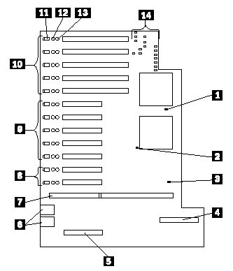
A simplified layout of the I/O board is shown in the following illustration.

|
1 |
System Reset jumper J8 |
|
2 |
Force PCI power-on for slot 11 jumper J9 |
|
3 |
Force System Power jumper J7 |
|
4 |
IDE connector |
|
5 |
System-management adapter slot |
|
6 |
USB 1 and USB 2 port connectors |
|
7 |
I/O function card slot |
|
8 |
Hot-plug 32-bit PCI slots 11 - 12 (bus C) |
|
9 |
Hot-plug 32-bit PCI slots 6 - 10 (bus B) |
|
10 |
Hot-plug 64-bit PCI slots 1 - 5 (bus A) |
|
11 |
Attention LED for PCI slot |
|
12 |
Attention LED for PCI slot |
|
13 |
Power LED for PCI slot |
|
14 |
I/O Board LEDs (see I/O Board LEDs) |
|
Search Keywords |
| |
|
Document Category |
Diagrams | |
|
Date Created |
02-11-98 | |
|
Last Updated |
18-01-99 | |
|
Revision Date |
18-01-2000 | |
|
Brand |
IBM PC Server | |
|
Product Family |
Netfinity 7000 M10 | |
|
Machine Type |
8680 | |
|
Model |
all | |
|
TypeModel |
| |
|
Retain Tip (if applicable) |
| |
|
Reverse Doclinks |