

|
145.801 bytes |
Service Hints & Tips |
Document ID: MNOK-3QJMBX |
Aptiva - How to reseat data and power cables for CD-ROM
Applicable to: World-Wide
Warning: The system board, processor, adapter cards, SIMMs, video memory modules, and upgrade processors can be damaged by electrostatic discharge. Use an electrostatic discharge (ESD) strap to establish personal grounding. If you don't have an ESD strap, establish personal grounding by touching a ground point with one hand before touching the static-sensitive components.
Note: Before removing the system cover, power off the system unit, unplug all power cords from electrical outlets, disconnect any interconnecting cables, and disconnect any telephone cords. The power supply might contain +5 V DC auxiliary power when the system is powered off. Be sure to unplug the power cord before working inside the system.
For 2134 and 2144 systems:
Remove the cover from the system as shown below:
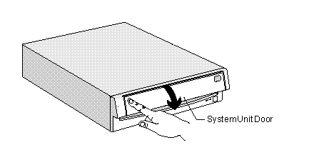
Push In on the Door to open.
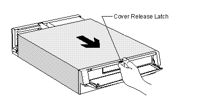
Squeeze the Cover Release Latch, then Pull Out on the Cover
For 2161, 2168, and 2176 systems:
Remove the cover from the system as shown below:
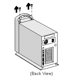
Unscrew the two screws behind the front handle.
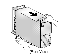
Pull Out on the Cover
For 2140 systems:
Remove the cover from the system as shown below:
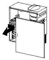
Remove service panel: Pull out on the rear tab to release the side service panel.
For 2136 and 2137 systems:
Remove the cover from the system as shown below:
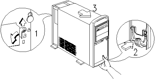
At rear of tower, move latch in toward middle of computer to unlatch. From the front of the tower, place hand, palm up under the bottom. Squeeze and pull to release that latch and slide cover off toward front of computer.
For systems with no media console:
1. Locate the data cable on the back of the CD-ROM drive. The data cable is a wide ribbon cable with a red stripe on one side. It should be connected to the CD-ROM drive at the connector labeled "IDE INTERFACE" in the figure below:

2. Pull the cable straight back out of the connector on the back of the CD-ROM. Trace the length of the cable to its terminus on the system board, and disconnect the cable from the system board connector. Make a note of the location of the system board connector and the orientation of the cable to facilitate the reconnection of the cable later.
3. Locate the data cable on the rear of the hard drive. The data cable is a wide gray ribbon cable that is identical to the CD-ROM drive data cable. Remove the cable from its connector on the hard drive, and then follow it along its length and disconnect the opposite end of the cable from the connector on the system board.
4. You should now have removed both data cables from the system. Take the hard drive data cable and attach the connector that had been connected to the rear of the hard drive to the rear of the CD-ROM drive. Attach the other end of the cable to the system board using the connector that had originally held the CD-ROM data cable. Both ends of the cable are keyed so that they can only be inserted one way.
5. Take the end of the CD-ROM data cable that had been attached to the rear of the CD-ROM drive and attach it to the rear of the hard drive. Attach the other end of the cable to the system board.
For 2159 and 2162 systems:
These media consoles are not considered as user-serviceable. However, the end-user can remove and reseat the media console cable at the tower and the media console host card inside the tower. It is recommended to replace the media console or to take the system to an IBM servicer for CD ROM service.
For 2142 systems:
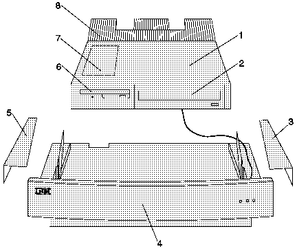
Media Console Assembly, Type 2142:
1. Media Console Top Cover & Console Assembly
2. CD-ROM or DVD-ROM Drive
3. Right Wing Cover
4. Media Console Base
5. Left Wing Cover
6. 3.5-in. 1.44 MB Diskette Drive
7. Client Card including On/Off switch (internal)
8. Media Console Rear Cover
1. With system turned off, remove the Media Console Rear-Cover (#8) by pushing down on cover with both thumbs and pushing cover to the rear.
2. Remove the Right and Left Wing Covers (#3 & 5) by pulling covers away from the side of the case.
3. Lift the Console Assembly straight up from the front and then pull it out of the hinge assembly. In order to gain access to the cable connectors in the Media Console Base (4), set the Console Assembly back down, slightly toward the front of the Media Console Base.
4. Squeeze the two end clips inward on the ribbon cables to the CD-ROM drive and to the Floppy drive and pull the cable connections upward to remove. It helps to alternate pulling on each side of the connector until it is removed.
5. Remove the two white power connector cables at the center. There is a clip on the back of each socket that holds the connector. If you place your thumbnail or similar tool in from the top and pull slightly to the rear, it will release the clip so that the connector may be pulled out with your other hand. Also, just to the left of the center of the Media Console Base, remove the CD ROM audio cable by pulling up on the small white connector.
6. The Console Assembly should now be separated from its base. At the rear of the CD-ROM drive, clamp both sides of the blue ribbon cable and work it out of its socket. This will give you access to the white power connector. Grasp it at the sides and work it out of its socket. Inspect them for physical damage.
7. Replace white power connector cable and blue ribbon cable connector into their sockets. Ensure that both cables are seated securely.
8. Reseat the two blue ribbon cables, the two white power cables, and the CD-ROM audio cables into their respective sockets on the Media Console Base. Ensure that the cables are seated securely.
9. Set Media Console Assembly into hinge sockets from a vertical position. Close Media Console Assembly.
10. Slide the Wing Covers from back to front into their slots. Slide the Rear Cover from back to front into its slots to complete the assembly process.
|
Search Keywords |
| |
|
Hint Category |
CD-ROM Drives, Hardware Installation/Configuration, Cables | |
|
Date Created |
08-01-98 | |
|
Last Updated |
11-01-99 | |
|
Revision Date |
11-01-2000 | |
|
Brand |
IBM Aptiva | |
|
Product Family |
Aptiva | |
|
Machine Type |
2134, 2136, 2137, 2140, 2142, 2144, 2159, 2161, 2162, 2168, 2176 | |
|
Model |
351; 353; 361; 440; 445; 446; 6R6; C21; J31; J3A; J3X; J51; J52; JDA; JSN; K01; K21; K22; K23; K31; K32; K52; K53; K62; K74; L01; L21; L22; L23; L31; L32; L52; L53; L6T; P01; P21; P22; P23; P31; P32; P52; P53; P62; E10; E11; E12; E13; E14; E15; E16; E20; E21; E22; E23; E24; E25; E26; E27; E30; E31; E32; E33; E34; E35; E36; E40; E42; E44; E45; E46; E54; E55; E56; E64; E65; E66; E03; E05; E06; E10; E11; E12; E13; E14; E15; E16; E17; E1F; E20; E21; E22; E23; E24; E25; E26; E27; E2F; E30; E31; E32; E33; E34; E35; E36; E37; E3F; E40; E41; E42; E43; E45; E46; E47; E4F; E50; E54; E64; E74; E84; L17; L27; L31; L35; L37; L3F; L45; L47; L51; L5H; L61; L6D; L71; LG1; LG2; LQ1; LQ2; LQ3; LV1; LV2; SQ1; SQ2; S34; S35; S36; S44; S45; S46; S57; S61; S62; S67; S6F; S6H; S6S; SG1; SG2; SQ1; SQ2; SV1; SV2; A10; A12; A14; C30; C31; C51; H55; H66; H67; H77; H78; H80; H81; H92; H93; K10; K20; K25; K26; K30; K33; K35; K40; K43; K45; K66; K67; K77; K78; K80; K81; K92; K93; KB0; KB1; KB2; KB3; KB4; KB5; KB6; KP1; KP2; KPA; KPB; KPC; KPD; KPE; KU0; KU1; KU2; KU3; KU4; KU5; KU6; L10; L11; L15; L16; L20; L30; L33; L35; L40; L43; L45; L55; L66; L67; L77; L78; L80; L81; L92; L93; LB0; LBD; LL1; LL2; LL3; LL4; LP0; LP1; LP2; LPA; LPB; LPC; LS0; LS1; LS2; LS3; LSA; LSB; LSC; LSD; M30; M31; M35; M50; M51; M52; M63; MB4; MB5; N30; N40; N41; OR6; OR7; OR8; OR9; P30; S15; S20; S82; S86; T82; U11; U15; U16; U33; U35; U43; U45; W30; WM1; WM2; X10; X17; X20; X27; X30; X40; X65; X70; X79; X88; X89; X90; XP1; XP2; Y10; Y17; Y20; Y27; Y30; Y65; Y70; Y78; Y79; Y84; Y88; Y89; Y90; YP1; YP2; Z10; Z17; Z20; Z27; Z30; 13R; 14R; 15R; 16R; 17R; 18R; 19R; 20R; B60; B65; B75; B80; B85; B95; S64; S66; S74; S76; S78; S7H; S80; S90; 21R; 22R; 24R; 25R; 38R; 460; 461; 462; 471; C3D; C3E; C85; C8E; C8F; C8H; C8M; C8X; C9E; C9F; C9S; C9X; D34; D64; D84; E34 E64; E84; F34; F64; F84; G66; G76; H66; H76; J66; J76; L81; L91; M81; M91; N63; N64; N74; N81; N91; T71; T81; T84; T85; T8B; T8C; T8E; T8F; T94; T95; T9D; T9E; TAE; TAF; 28R; 29R; 30R; 31R; 33R; 35R; 37R; 41R; 54S; 56S; 57S; 58S; B86; B87; B97; D81; D91; E81; E91; G86; G96; G97; H86; H96; P81; P91; Q3C; Q81; Q91; S35; S3C; S8C; S8H; S9C; S9H; S9M; U81; U91; V86; V96; X8C; X9D; A40; A44; A45; A50; A51; A52; A90; A92; A94; C40; C41; C45; C53; C61; H89; H90; K50; K55; K60; K65; K66; K89; K90; L50; L55; L60; L65; L66; L89; L90; LL5; M40; M41; M53; M54; M55; M56; M57; M58; M60; M61; M62; M70; M71; M72; M91; N50; N51; N60; N61; N71; S50; S55; S64; S65; S74; S75; SW2; U55; U65; U66; W37; W47; X37; X47; Y37; Y40; Y47; Z37; Z40; Z47; 352; 354; 355; 356; 362; 363; 364; 372; 374; 381; 382; 384; 392; 442; 443; 447; 449; 454; 6R8; 6R9; 7R0; 7R1; 7R2; 7R3; 7R6; 7R7; 7R9; 8R1; 8R6; 8R8 ; 9R1; 9R2; 9R3; 9R4; 9R5; 9R6; C23; C31; C32; C33; C35; C3X; C53; C55; C5X; C65; C66; C67; C6B; C6D; C6E; C6V; C6X; C6Y; C6Z; C73; C77; C7X; F23; F31; F32; F33; F35; F67; F6B; H54; H55; H56; H5E; H5F; H64; H65; H6D; H6E; H6F; H7E; H7F; H7G; J33; J35; J3C; J3E; J3K; J3L; J3V; J3W; J3Y; J3Z; JCL; L62; T01; T33; T34; T62; T63; T65; T71; V34; V65; V71; W33; W55; W65; X01; X31; X33; X34; X52; X62; X63; X65; X71; Y01; Y04; Y31; Y33; Y34; Y52; Y62; Y63; Y65; Y71; Z01; Z31; Z33; Z34 Z52; Z62; Z63; Z65; Z71 | |
|
TypeModel |
| |
|
Retain Tip (if applicable) |
| |
|
Reverse Doclinks |