

|
179.957 bytes |
Service Hints & Tips |
Document ID: YAST-3K3K3K |
ADF Color Scanner - Hardware Installation
Applicable to: World-Wide
Highlights:
* 10-page automatic document feed
* 1200 dpi resolution
* Emulates HP ScanJetIIcx
* Product Number: 25H6629
* FRU Numbers: 25H6641(adapter), 25H6648 (scanner.)
System Requirements:
* IBM or IBM compatible i80386 (or Higher) ISA System
* 8 or 16bit ISA bus expansion slot
* 4MB of RAM
* 10MB free space on hard drive
Software Requirements:
* DOS 3.3 or later and Windows 3.1 or later
* Windows 95
* OS/2 3.0 with Win-OS/2
HARDWARE INSTALLATION:
Unpacking the Adapter:
1. Turn off all attached devices; then turn off the computer. Disconnect the power cords from the computer and all attached devices.
2. Touch the antistatic bag containing the adapter to the power supply or metal chassis of the system.
3. Remove the adapter from the antistatic bag, and handling it by the edges. Do not touch the exposed electronic components on the adapter. Note: Try to complete Step 2 and Step 3 without putting the adapter down. If you must put the adapter down, place it on the antistatic bag on a resilient surface, such as a magazine.
Verifying the I/O Address:
Your computer microprocessor uses the internal I/O(input/output) address to communicate with the adapter. For most computers, the factory installed I/O address, I/O 270, is the correct choice; however, if you know that this address is in use, you must select a new I/O address. The small black jumpers that slide onto the metal pin(s) on the adapter are used to set the internal I/O address connections. Before installation of the adapter, verify the I/O address and reset, if necessary.
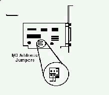
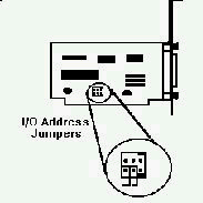
1. Locate the jumper block labelled JP1 on the adapter.
A. If the jumper block has 6 pins, verify that the factory installed address I/O 270 is set as shown.

B. If the jumper block has 9 pins, verify that the factory installed address I/O 270 is set as shown.
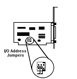
2. To change the I/O address select a new address from the choices shown below. Note: I/O addresses 360 and 3 are
most commonly available.
A. For the 6-pin jumper block...
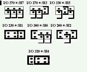
B. For the 9-pin jumper block...
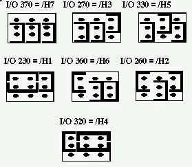
3. Remove each jumper, pulling it off the pins using care not to damage the jumper or the pins. Line up the holes of each jumper with the pin(s) corresponding to the desired I/O address. Place each jumper on the pin(s) and push the jumper firmly onto the pin(s).
Installing the Adapter:
1. Remove the computer cover and find an available 8-bit or 16-bit ISA bus expansion slot.
2. Install the adapter in the expansion slot.
3. Attach one end of the interface cable to the scanner and the other end to the adapter. Ensure that the cable is securely attached and the adapter remains properly seated in the expansion slot.
4. Replace the computer cover.
5. Restart the computer. The power indicator light on the scanner should illuminate.
6. If an I/O addressing error occurs during the restart of the computer, refer to "Verifying the I/O Address" to reset the I/O address.
Keywords: OBI ADF Color Scanner 25H6629 Hardware Installation
|
Search Keywords |
| |
|
Hint Category |
Hardware Installation/Configuration | |
|
Date Created |
17-07-97 | |
|
Last Updated |
12-04-99 | |
|
Revision Date |
12-04-2000 | |
|
Brand |
IBM Options | |
|
Product Family |
Input Devices | |
|
Machine Type |
Scanners | |
|
Model |
25H6629 | |
|
TypeModel |
| |
|
Retain Tip (if applicable) |
| |
|
Reverse Doclinks |