
|
58.503 bytes |
Service Hints & Tips |
Document ID: GSMH-3E8K69 |
PC Server 325/330/704 - Adapter cable to system board connections
Applicable to: World-Wide
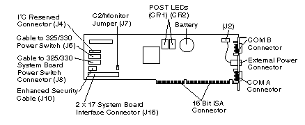
Adapter Cable to System Board Connections:
|
Note: |

PC Server 325:
Refer to the IBM PC Server 325 Hardware Maintenance Manual for system board layout.
- 34-pin cable from Adapter (J16) to System Management Cable Connector (J19) on system board.
- 16-pin cable from Adapter (J8) to Operator Panel Connector (J7) on system board.
- Cable from Operator Panel to Adapter (J6).
PC Server 330:
Refer to 'System Board— for system board layout.
- 34-pin cable from Adapter (J16) to System Management Cable Connector (J19) on system board.
- 16-pin cable from Adapter (J8) to Operator Panel Connector (J7) on system board.
- Cable from Operator Panel to Adapter (J6).
PC Server 704:
Refer to the IBM PC Server 704 Hardware Maintenance Manual for system board layout.
|
Note: |
- 26-pin end of the systems management cable to the System Management Cable Connector (J3G1) on the system board.
- 34-pin end of the systems management cable to Adapter connector (J16).
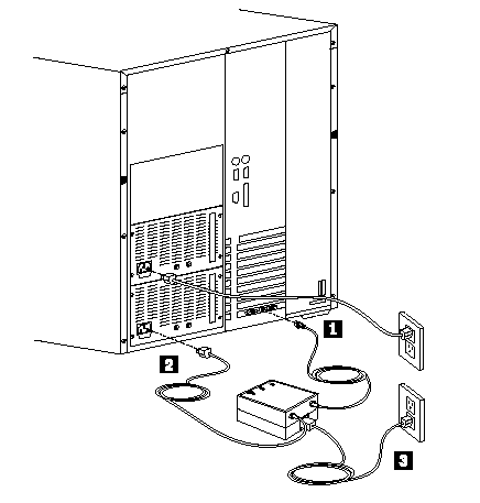
- Connect the External Power Control Unit control cable, 1 , external power control unit power cord, 2, and system power
cords, 3 , as shown:

|
Note: |
External Power Control Unit Operation and Indicators:
The external power control unit provides power to the system under control of the adapter.

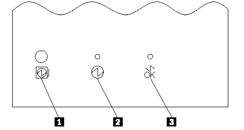
The Power Status LED 2 On indicates power is enabled to the system. The Power Status LED Off indicates power is disabled to the system.
The Cable Attached LED 3 On indicates the power unit control cable is connected to the adapter. The Cable Attached LED Off indicates the external power control unit control cable is not connected to the adapter.
If system power from the external power control unit is disabled by the adapter, press the external power control unit power on button 1 to enable system power from the external power control unit.
|
Power Status LED 2 |
Cable Attached LED 3 |
Indicates |
Action/FRU |
|
On |
On |
System power is enabled and the external power control unit signal cable is connected to adapter. |
None |
|
Off |
On |
The adapter has caused system power to be removed and the external power control unit signal cable is connected to adapter. |
1. Press the external power control unit power on button 1 to restore system power. |
|
Off |
External power control unit signal cable is not connected to adapter. |
1. Connect the cable to the adapter. |
|
Search Keywords |
| |
|
Hint Category |
Adapter Cards, Hardware Maintenance Information | |
|
Date Created |
12-02-97 | |
|
Last Updated |
16-07-98 | |
|
Revision Date |
14-07-99 | |
|
Brand |
IBM PC Server | |
|
Product Family |
PC Server 325, PC Server 330, PC Server 704 | |
|
Machine Type |
8639, 8640, 8650 | |
|
Model |
| |
|
TypeModel |
| |
|
Retain Tip (if applicable) |
N/A | |
|
Reverse Doclinks |