
|
76.786 bytes |
Product Information |
Document ID: DDSE-44JM7M |
Netfinity 7000 - Configuration Conflicts
Applicable to: World-Wide
Configuration Conflicts
The resources used by the server consist of IRQs, DMA channels, I/O ports (for example, serial and parallel), and memory. This information is useful when a resource configuration conflict occurs.
Conflicts in the configuration occur if:
An installed device requires the same resource as another device. (For example, if you install an ISA network adapter and an EISA network adapter, both requesting IRQ 5, you can configure only one of the adapters.)
A device resource is changed (for example, changing jumper settings).
A device function is changed (for example, assigning COM 1 to two different serial ports). An installed software program requires the same
resource as a hardware device (for example, a device driver that uses the address required by the SVGA video controller).
The steps required to resolve a configuration error depend on the number and variety of hardware devices and software programs install. If a hardware configuration error is detected, a configuration error message appears after the server completes POST, but before the operating system starts. You can bypass the error or start one of the configuration utility programs. Press Esc to bypass the error and load the operating system.
The Setup program and the System Configuration Utility program configure only the system hardware. These programs do not consider the requirements of the operating system or the application programs. See Resolving Software Configuration Conflicts on page 34 for additional information.
Configuring EISA, ISA, and PCI Adapters
Before installing a new device or program, read the documentation that comes with it. Reading the instructions helps you to determine the steps required for installation and configuration. The following is a preview of the actions that might be required to configure the server.
If you want to install PCI adapters, they must be 5-volt devices.
Run the System Configuration Utility program when you first set up and configure the system, if you have added or removed any hardware options, or if you receive an error message instructing you to do so.
1. Start the System Configuration Utility program and:
a. Record the current configuration settings.
b. Install configuration files ( .CFG).
See Starting the System Configuration Utility Program on page 45 and Recording the System Configuration Utility Program Settings on page 49 for information about starting the System Configuration Utility program and recording current configuration settings. Instructions for installing configuration files are also included in Starting the System Configuration Utility Program on page 45. If the .CFG files did not come with the adapter, see Configuration Files.
2. Set jumpers or switches on the system board.
3. Set jumpers or switches on the device. See the instructions that come with the adapter.
4. Install the adapter in the server. See Adapters on page 60.
5. Install software programs. See the installation instructions that come with the software.
6. Resolve configuration conflicts.
See Configuration Conflicts on page 26.
ISA or EISA Option Diskettes: Some ISA and most EISA devices come with Option Diskettes. These diskettes can contain any or all of the following types of information:
Configuration files ( .CFG)
- Diagnostic files
- Device drivers
Sample applications (mini-applications)
Configuration Files: The server requires a configuration file to configure ISA or EISA adapters. The configuration file reserves the system resources that the adapter needs to function properly. Some ISA adapters come with a diskette that contains the .CFG file for the
adapter. The System CD-ROM contains the .CFG file for some devices and options. If an Option Diskette comes with the device, refer to the device documentation for instructions to configure the device.
If you want to install ISA adapters that did not come with their own .CFG files, use the System Configuration Utility program to create a unique .CFG file for each adapter.
Note :
The unique .CFG files are slot sensitive. That is, they should not be used to configure identical adapters in multiple systems unless you install the adapters in the same expansion slots within each system.
To create a unique .CFG file for an ISA adapter:
1. At the System Configuration Utility program Main Menu screen, select Add and Remove Boards.
2. Press F6 (Define ISA).
3. At the ISA Definition screen, type in the adapter manufacturer and description (for example, IBM Token Ring).
Refer to the adapter documentation for information about specific configuration parameters, such as interrupt request levels (IRQs) or direct memory access (DMA) channels, that are required for the adapter. Then, follow the instructions on the screen to enter the appropriate parameters.
4. After you type in all of the appropriate parameters, press F10 to save the data.
5. At the Main Menu screen, select Save Configuration to save the configuration in NVRAM.
Note : Save the configuration files to a diskette for backup.
Diagnostic Files: The Diagnostic program that comes with the server is the primary method of testing the server. Some optional devices and adapters come with option-specific diagnostic files. These files provide a more specialized test of the option. Refer to the documentation that comes with the option for information about installing and running option-specific diagnostics.
Device Drivers: Device drivers are programs designed to support a specific type of hardware device. They provide instructions that enable the server to interact with the device, or to take advantage of a device's special features. The device driver might ship with the operating system, the application program, or on an option diskette. Not all devices require device drivers. Refer to the documentation that comes with the option for additional information.
Sample Applications: Some optional devices provide small applications or sample files. These applications demonstrate the capabilities of the device and serve as software examples for programming the device. Refer to the documentation that comes with the option for additional information.
Configuring the Advanced Systems Management Adapter
The Advanced Systems Management Adapter comes completely installed and configured. Use these instructions only if you need to change the default parameters to meet your specific processing requirements. This process can be divided into two parts:
Configuring system resources
Configuring the adapter
Configuration Considerations:
The adapter uses only adapter COM B for external communication, therefore a modem or null-modem cable must be connected to adapter COM B. If you want to share adapter COM B with the system, adapter COM B must be assigned one of the following I/O addresses:
3F8 (COM 1)
2F8 (COM 2)
3E8 (COM 3)
2E8 (COM 4)
If you want adapter COM B dedicated to the adapter only, you must disable adapter COM B through the adapter configuration program to prevent the system from accessing it. The adapter comes configured with adapter COM B disabled.
The adapter COM A is not used by the adapter. If you want the system to use adapter COM A, the adapter must be configured through the adapter configuration program.
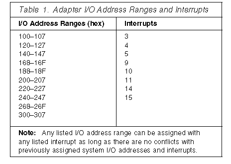
Each port I/O address covers eight contiguous address bytes as shown in Table 1 on page 30. Make sure there are no conflicts between the adapter port I/O addresses and interrupts that you configure, and previously assigned system I/O addresses and interrupts.
The adapter comes configured with I/O address 200 205 and interrupt 5.
The adapter can be configured to the following I/O address ranges and interrupts:

Configuring System Resources: Use the System Configuration Utility program to assign system resources to the Advanced Systems Management Adapter. See System Configuration Utility Program on page 44 for detailed instructions.
1. Start the System Configuration Utility program and select Change Configuration Settings; then, select the adapter and press F6 to change adapter configuration values.
2. Refer to the list in Table 1 and assign I/O addresses and interrupts for the adapter ports.
Configuring the Adapter
1. Use the ServerGuide package to create the Advanced Systems Management Adapter configuration diskette. Refer to the information that came with ServerGuide for instructions.
2. Press the Power On/Off Button to power-off the server.
3. Remove the server top cover.
4. Make sure the adapter configuration diskette is not write protected.
5. Insert the adapter configuration diskette into your primary diskette drive.
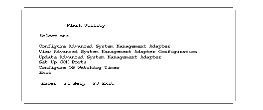
6. Press Ctrl+Alt+Del to restart your system. The program displays the Flash Utility menu:

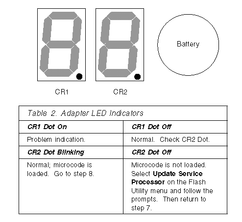
7. Check the dot on the two LED displays on the adapter for the indications listed in Table 2.

8. Refer to the configuration data you recorded and complete the following steps.
a. Choose Configure Advanced System Management Adapter from the Flash Utility menu and select the port and IRQ that you entered in the configuration data worksheet. The utility program writes an SM.INI file to the diskette. This file is used during the device driver installation.
b. Follow the on-screen prompts and choose Setup COM Ports from the Flash Utility menu. Select the COM port I/O addresses and interrupts that you entered on the configuration worksheet.
9. Follow the on-screen prompts to exit from the adapter configuration utility program.
10. Replace the server top cover.
|
Search Keywords |
| |
|
Document Category |
Configuration | |
|
Date Created |
27-01-99 | |
|
Last Updated |
27-01-99 | |
|
Revision Date |
27-01-2000 | |
|
Brand |
IBM PC Server | |
|
Product Family |
Netfinity 7000 | |
|
Machine Type |
8651 | |
|
Model |
| |
|
TypeModel |
| |
|
Retain Tip (if applicable) |
| |
|
Reverse Doclinks |