
|
23.588 bytes |
Product Information |
Document ID: MCGN-45WQJ4 |
Netfinity 5500 M20 - Memory board component locations
Applicable to: World-Wide
Memory board component locations
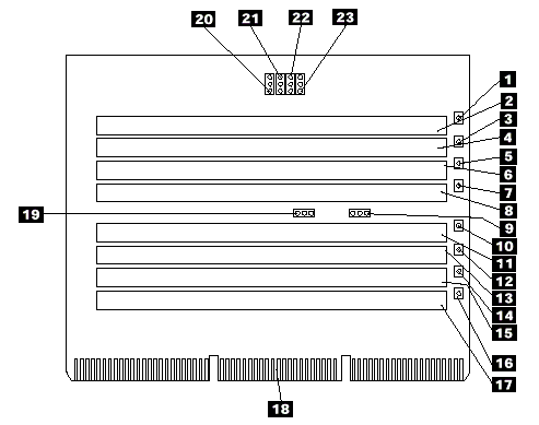
A layout of the memory board is shown in the following illustration.

1 DIMM 1 error LED (CR5)
2 DIMM connector 1 (J1)
3 DIMM 2 error LED (CR6)
4 DIMM connector 2 (J2)
5 DIMM 3 error LED (CR3)
6 DIMM connector 3 (J3)
7 DIMM 4 error LED (CR2)
8 DIMM connector 4 (J4)
9 Reserved (J13)
10 DIMM 5 error LED (CR7)
11 DIMM connector 5 (J5)
12 DIMM 6 error LED (CR4)
13 DIMM connector 6 (J6)
14 DIMM 7 error LED (CR1)
15 DIMM connector 7 (J7)
16 DIMM 8 error LED (CR8)
17 DIMM connector 8 (J8)
18 Memory board connector to processor board
19 Reserved (might not be present) (J15)
20 Reserved (J12)
21 Reserved (might not be present) (J14)
22 Reserved (J9)
23 Reserved (J11)
|
Search Keywords |
| |
|
Document Category |
Diagrams | |
|
Date Created |
12-03-99 | |
|
Last Updated |
21-05-99 | |
|
Revision Date |
16-03-2000 | |
|
Brand |
IBM PC Server | |
|
Product Family |
Netfinity 5500 M20 | |
|
Machine Type |
8662 | |
|
Model |
ALL | |
|
TypeModel |
| |
|
Retain Tip (if applicable) |
| |
|
Reverse Doclinks |