
|
80.186 bytes |
Product Information |
Document ID: DDSE-42CSR4 |
Netfinity 3000 - Input / Output Connectors
Applicable to: World-Wide
Input/Output Connectors
Input/output (I/O) connectors provide ports for transferring information into and out of the server. You can connect a variety of I/O devices to the server, including a monitor, keyboard, mouse, and printer. For more information on the ports and their specific technologies, see "External Options".
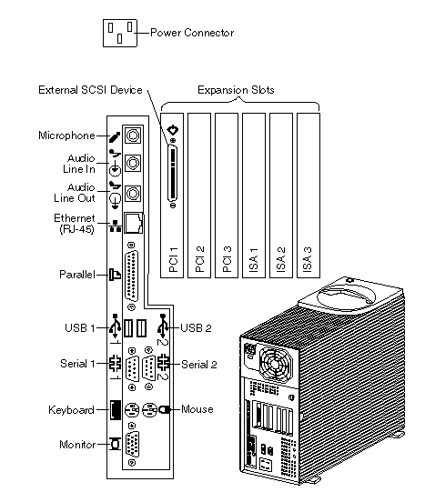
At the rear of the server is a panel that provides access to I/O connectors. Adapters installed in expansion slots might also provide I/O connectors. The following illustration shows the I/O connectors that come with the server.

Power Connector: The server power cable connects here.
 External SCSI Device Connector: External SCSI devices attach here. For more information, see "SCSI Drives", "External SCSI Devices", and "SCSI Connectors".
Expansion Slots: Cables to the external connectors on installed ISA and PCI adapters connect here. For information about expansion slots and adapters, see "Adapters".
|
Note |
 Microphone: This connector is used to attach a microphone to the server when you want to record voice or other sounds on the hard disk. This connector can also be used by speech-recognition software.
 Audio Line In: This connector is used to send audio signals from an external device (such as a CD player or stereo) to the server so that the signals can be recorded on the hard disk.
 Audio Line Out: This connector is used to send audio signals from the server to external devices, such as stereo-powered speakers with built-in amplifiers, headphones, multimedia keyboards, or the audio line-in jack on a stereo system. To hear audio, you must connect one of these external devices to the audio line-out connector on the server.
|
Note |
 Ethernet Connector: An unshielded, twisted-pair (UTP) cable with an RJ-45 connector attaches here to the 10/100 Ethernet controller on the system board.
For information on the Ethernet controller, see "Configuring the Ethernet Controller". For more information on the Ethernet connector, see "Ethernet Connector". For information on cables, see "Specifications (Ethernet Cable)".
The server contains a diagnostic light-emitting diodes (LEDs) for the Ethernet connector located on the rear panel of the server.
- When the green LED is on, it indicates that the Ethernet controller is connected to a hub or switch and is receiving link pulses. This LED is also known as the Link OK light.
- When the amber LED is on, it indicates that the Ethernet network is operating at 100 Mbps. When this LED is off, it indicates that the Ethernet network is operating at 10 Mbps.
 Parallel Connector: A signal cable for a parallel device, such as a printer, connects here.
 Universal Serial Bus (USB) Connectors: I/O devices with universal serial bus (USB) connectors attach
to USB connector 1 and connector 2. You need a 4-pin cable to connect a device to these ports.
 Serial Connectors: Signal cables for modems or other serial devices attach to the 9-pin serial connectors of serial ports 1 and 2. See "Serial Port Connectors" for port assignment information.
 Mouse Connector: The mouse cable connects here. This connector is sometimes called the auxiliary-device port.
 Keyboard Connector: The keyboard cable connects here.
 Monitor Connector: The monitor signal cable connects here.
|
Search Keywords |
| |
|
Document Category |
Diagrams | |
|
Date Created |
18-11-98 | |
|
Last Updated |
09-12-98 | |
|
Revision Date |
09-12-99 | |
|
Brand |
IBM PC Server | |
|
Product Family |
Netfinity 3000 | |
|
Machine Type |
8476 | |
|
Model |
ALL | |
|
TypeModel |
| |
|
Retain Tip (if applicable) |
| |
|
Reverse Doclinks |