
|
102.703 bytes |
Parts Information |
Document ID: DDSE-44JKZQ |
Netfinity 7000 - Memory Board / Memory-Module Kits
Applicable to: World-Wide
Memory Board/Memory-Module Kits

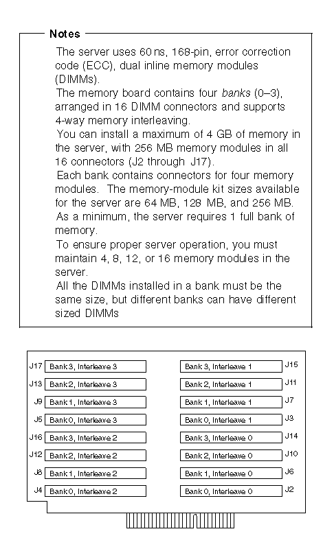
Several examples of memory module configurations are:
The base memory is four 64 MB DIMMs. The DIMMs are installed in bank 0, connectors J2-J5. You want four 64 MB DIMMS, eight 128 MB DIMMs, and four 256 MB DIMMs in the server. Leave the 64 MB DIMMS in bank 0, connectors J2-J5 and install the 128 MB DIMMS in bank 1, connectors J6-J9 and bank 2 connectors J10-J13 and the 256 MB DIMMs in bank 3, connectors J14-J17.

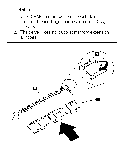
1 Memory module (DIMM)
2 Retaining clip
3 Memory-module connector
To install the memory module:
1. Place the memory board, component-side up, on a flat, static-protective surface.
2. Locate the memory-module connectors on the memory board.
3. Touch the static-protective package containing the memory-module kit to any unpainted metal surface on the server. Then, remove the memory-module kit from the package.
4. Install the kit:
|
Attention |
|
Note: |
|
Attention |
|
Search Keywords |
| |
|
Document Category |
Memory | |
|
Date Created |
27-01-99 | |
|
Last Updated |
27-01-99 | |
|
Revision Date |
27-01-2000 | |
|
Brand |
IBM PC Server | |
|
Product Family |
Netfinity 7000 | |
|
Machine Type |
8651 | |
|
Model |
| |
|
TypeModel |
| |
|
Retain Tip (if applicable) |
| |
|
Reverse Doclinks |