
|
13.333 bytes |
Service Hints & Tips |
Document ID: GKEY-3H4JN9 |
PCServer704 - Diagrams (Intrusion Alarm)
Applicable to: World-Wide
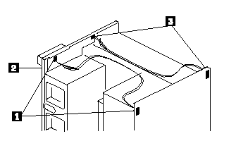
Intrusion Alarm Switch and Cable
|
Note | |
|
Cables are on the front-facing side of the front panel control board. |

|
1. |
Connector J5 on the front panel control board; switch located at the back near the power supply. |
|
2. |
Connector J2 on the front panel control board; switch located at the back above the board cage area. |
|
3. |
EMI door switch location (not shown); direct contact no cable. |
|
Search Keywords |
| |
|
Hint Category |
Hardware Maintenance Information | |
|
Date Created |
15-05-97 | |
|
Last Updated |
28-05-98 | |
|
Revision Date |
27-05-99 | |
|
Brand |
IBM PC Server | |
|
Product Family |
PC Server 704 | |
|
Machine Type |
8650 | |
|
Model |
Various | |
|
TypeModel |
| |
|
Retain Tip (if applicable) |
| |
|
Reverse Doclinks |