
|
49.950 bytes |
Service Hints & Tips |
Document ID: DJON-3LVPK6 |
TP 770 - General Checkout Guide
Applicable to: World-Wide
Use the following procedure as a guide for computer problems.
Note: The diagnostic tests are intended to test only IBM products. Non-IBM products, prototype cards, or modified options can give false errors and invalid system responses.
1. Obtain the failing symptoms in as much detail as possible.
2. Verify the symptoms by attempting to re-create the failure by running the diagnostic test or by repeating the same operation.
Note: To run the diagnostics, refer to Running the Diagnostics.
3. Use the following table with the verified symptom to determine which section to go to. Search the symptoms column, and find the description that best matches your symptom.
|
Symptoms (Verified) |
Go To |
|
Power failure. (The power indicator does not go on or stay on.) |
Power Systems Checkout |
|
POST does not complete. No beeps or error codes are displayed. |
Symptom-to-FRU Index and then go to No Beep Symptoms |
|
The configuration is not the same as the installed devices. |
Checking the Installed Devices List |
|
POST beeps, but no error codes are displayed. |
Symptom-to-FRU Index and then go to Beep Symptoms |
|
POST detected an error and displayed numeric error codes. |
Symptom-to-FRU Index and then go to Numeric Error Codes |
|
The diagnostic test detected an error and displayed a FRU code. |
FRU Codes |
|
Other symptoms (such as LCD display problems). |
Symptom-to-FRU Index and then go to Other Symptoms |
|
Symptoms cannot be re-created (intermittent problems). |
Symptom-to-FRU Index and then go to Intermittent Symptom |
If the problem does not recur, recheck the connector. If the problem is not corrected, replace the device, and then the system board.
Memory Checkout
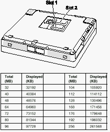
DIMMs are available for increasing memory capacity. You can install a 64-MB 2-bank DIMM in slot 1. If you try to install it in slot 2, it will not be recognized as a 64-MB DIMM.

Memory errors might stop system operations, show error messages on the screen, or hang the system.
Use the following procedure to isolate memory problems:
1. Power off the computer and remove any installed DIMM from its slots.
2. Press and hold the F1 key; then power on the computer. Hold the F1 key down until the Easy-Setup menu appears.
3. Select Test and press Enter.
4. Select Memory and press Enter to run the memory test on base memory. If an error appears, replace the system board.
5. Power off the computer and reinstall the DIMM; then power on the computer. Verify the memory size; then test the memory. If an error appears, replace the DIMM.
If memory problems occur intermittently, use the loop option to repeat the test. When the test detects an error, an error log is printed on the printer connected to the parallel port. See Displaying the Error Log for more information.
Flash Memory Update: System setup programs and diagnostic tests are stored in flash memory. A flash memory update is required for the following conditions:
- New versions of system programs
- New features or options
To update the flash memory, do the following:
1. Get the appropriate diskette containing the update.
2. Insert the System Program Service diskette into drive A, and power on the computer with AC power and a fully charged battery.
3. Select Update system programs from the menu.
Modem (DSP) Checkout
1. Go to the diagnostic menu by selecting Test in the Easy-Setup menu.
2. Select DSP and run the diagnostic tests.
3. If the test detects a DSP problem, replace the modem card.
Power Systems Checkout
To determine whether a power systems problem is due to the AC Adapter or the battery pack, do the following:
1. Remove the battery pack.
2. Connect the AC Adapter and check that power is supplied.
3. Disconnect the AC Adapter and install the charged battery pack; then check that power is supplied by the battery pack. If the problem is due to the AC Adapter, go to Checking the AC Adapter. If the problem is due to the battery pack, go to
Checking the Battery Pack. If the problem is not due to the AC Adapter or battery pack, go to the following sections:
- Checking the Backup Battery (Nonrechargeable)
- Checking the Standby Battery (Rechargeable)
Checking the AC Adapter: You are here because the computer fails only when the AC Adapter is used. If the power problem occurs only when AC Adapter is used with a port replicator, replace the replicator.
If the power-on indicator does not turn on, check the power cord of the AC Adapter for correct continuity and installation.
1. Unplug the AC Adapter cable from the computer and measure the output voltage at the plug of the AC Adapter cable. See the following figure:

|
Pin |
Voltage (V dc) |
|
1 |
+15.5 to +17.0 |
|
2 |
Ground |
If the voltage is correct, make sure the connection between DC/DC card and system board is not loose. Replace the DC/DC card. If the problem is not corrected, replace the system board. If the problem persists, go to Undetermined Problems. If the voltage persists, go to the next step.
2. Unplug the AC Adapter cable from the AC power outlet and wait 5 minutes or longer to allow the overvoltage protection circuit to be fully discharged and initialized.
3. Plug the AC Adapter cable into the AC power outlet.
4. Measure the output voltage of the AC Adapter.
5. If the voltage is still not correct, replace the AC Adapter.
Note: An audible noise from the AC Adapter does not always indicate a defect.
Checking the Battery Pack: If the battery pack has a problem, do the following:
1. Power off the computer.
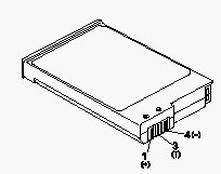
2. Remove the battery pack and measure the voltage between battery terminals 1 (+) and 4 (N). See the following figure:

|
Terminal |
Voltage (V dc) / Signal |
|
1 |
+0 to +13.5 |
|
2 |
Send |
|
3 |
Thermal |
|
4 |
Ground (N) |
|
5 |
Select |
Note: Signal lines not used in these steps are used for communication between the system and the battery.
3. If the voltage is less than +11.0 V dc, the battery pack has been discharged. Recharge the battery pack. If the voltage is still less than +11.0 V dc after recharging, replace the battery.
Note: If the voltage of the battery pack is 0 V, it is defective.
4. If the voltage is more than +11.0 V dc, measure the resistance between battery terminals 3 and 4. The resistance must be 4 to 30 K ohm. If the resistance is not correct, replace the battery pack. If the resistance is correct, replace the DC/DC card.
Checking Operational Charging
Note:
Battery charging will not start until the Fuel-Gauge shows that less than 95% of the total power remains; with this condition the battery pack will charge to 100% of its capacity. This restriction protects the battery pack from being overcharged or from having a shortened life.
To check operational charging, use a discharged battery pack or a battery pack that has less than 50% of the total power remaining when installed in the computer. Power on the computer while it is connected to the AC Adapter. If the battery status indicator does not turn on, power off the computer, remove the battery pack and let the battery pack return to room temperature. Reinstall the battery pack, and power on the computer (still connected to the AC Adapter). If the charge indicator still does not turn on, the battery pack should be replaced.
Checking the Backup Battery (Non-rechargeable)
1. Power off the computer and unplug the AC Adapter from the computer.
2. Open the DIMM cover.
3. Remove the backup battery. (Refer to 1050 Backup Battery or DIMM to remove the battery.)
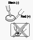
4. Measure the voltage of the backup battery connector. See the following figure:

|
Wire |
Voltage (V dc) |
|
Red |
+2.5 to +3.7 |
|
Black |
Ground |
If the voltage is correct, replace the system board.
If the voltage is not correct, the backup battery has been discharged. Replace the backup battery. If the backup battery discharges quickly after replacement, replace the system board.
Checking the Standby Battery (Rechargeable)
1. Power off the computer and unplug the AC Adapter from the computer.
2. Remove the battery pack and keyboard.
3. Remove the standby battery. (Refer to 1100 Standby Battery to remove the battery.)
Attention:
Be careful not to cause a short circuit when measuring the voltage.
4. Measure the voltage of the standby battery. If the voltage between red and black wire of the battery is 3.5 V dc or greater, the voltage is correct. Go to step 10 to verify standby battery operation. If the voltage is less than 3.5 V dc, go to the next step.
5. Plug the AC Adapter into the computer and power on the computer.
Attention:
Be careful not to cause a short circuit when measuring the voltage.
6. With the battery unplugged, measure the output voltage at the connector.

|
Pin |
Voltage (V dc) |
|
+ |
+4.0 |
|
N |
Ground |
|
Search Keywords |
| |
|
Hint Category |
Hardware Maintenance Information | |
|
Date Created |
13-09-97 | |
|
Last Updated |
17-08-98 | |
|
Revision Date |
14-08-99 | |
|
Brand |
IBM ThinkPad | |
|
Product Family |
ThinkPad 770 | |
|
Machine Type |
9548, 9549 | |
|
Model |
All | |
|
TypeModel |
| |
|
Retain Tip (if applicable) |
| |
|
Reverse Doclinks |