
|
401.095 bytes |
Service Hints & Tips |
Document ID: LWIK-3SML62 |
TP 365C/CS/CD/CSD/E/ED - FRU removals and replacements
Applicable to: World-Wide
FRU Removals and Replacements
The system board is sensitive to, and can be damaged by, electrostatic discharge. Establish personal grounding by touching a ground point with one hand before touching these units.
An electrostatic discharge (ESD) strap must be used to establish personal grounding.
Do not damage any parts. Only certified, trained personnel should service the computer.
The arrows in the 'Removals and Replacements— section show the direction of movement to remove a FRU, or to turn a screw to release the FRU. The arrows are marked in numeric order, in square callouts, to show the correct sequence of removal.
When other FRUs must be removed before removing the failing FRU, they are listed at the top of the page.
To replace a FRU, reverse the removal procedure and follow any notes that pertain to replacement. See 'Locations— for internal cable connections and arrangement information.
When replacing a FRU, use the correct screw size as shown in the procedures.
1) Before the computer is powered-on after FRU replacement, make sure all screws, springs, or other small parts, are in place and are not left loose inside the computer. Verify this by shaking the computer and listening for rattling sounds. Metallic parts or metal flakes can cause electrical short circuits.
2) The battery pack contains small amounts of nickel. Do not disassemble it, throw it into fire or water, or short-circuit it. Dispose of the battery pack as required by local ordinances or regulations.
3) Before removing any FRU, power-off the computer, unplug all power cords from electrical outlets, remove the battery pack, and then disconnect any interconnecting cables.
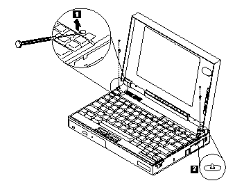
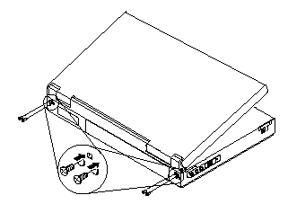
1010 Rear Connector Door
Open the door, then push down on the centre of the door to remove it.

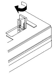
1015 Foot
To replace the foot :
Align the foot in the open position with one pivot pin in its hinge in the cover base.
Press the other pivot pin into position by rotating the foot as shown.
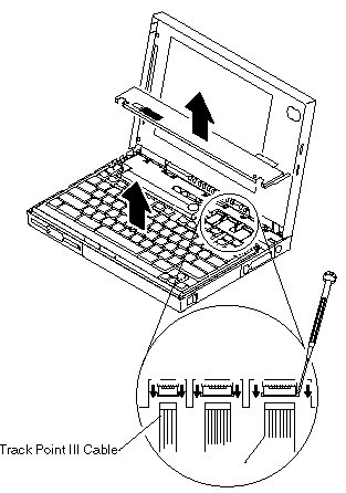
1020 Battery Pack
Disconnect the AC Adapter.
Open the computer.
Release the keyboard latches and raise the keyboard.
Be careful the computer does not fall over backwards as you remove the battery
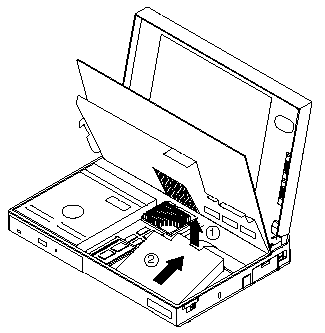
1030 SO-DIMM/Memory Board
To remove the optional SO-DIMM, release the latches as shown, then remove the SO-DIMM card.
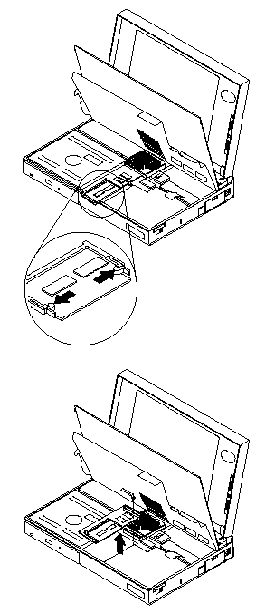
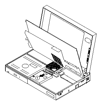
1040 Hard Disk Drive
Battery Pack (1020)
Memory Board (1030)
Attention
Do not drop or apply any shock to the Hard Disk drive. The hard disk drive is sensitive to physical shock. Incorrect handling can cause damage and permanent loss of data on the hard disk. Before removing the hard disk drive, have the user make a backup copy of all the information on the hard disk. Never remove the hard disk drive while the system is operating or is in suspend mode.
1050 Keyboard Unit
Battery Pack (1020)
Attention
During removal and replacement procedures, pay special attention to the LCD Suspend Switch. Be sure the LCD Suspend Switch actuator is properly aligned with the hole in the cover.
1. Remove the Plastic Upper cover as shown.
2. Lift the Keyboard as shown
Attention
The keyboard cables are fragile and can be damaged. Do not pull on the keyboard cables. Pull on the connectors only.
Important
When replacing the keyboard, check that the three cables are clean, and inserted straight and fully into the connectors.
Test all the keyboard keys before returning the computer to the customer.
When replacing the top cover -
Be sure the tabs on the back of the top cover are seated in the bottom of the LCD display
Be sure the LCD Suspend Switch actuator is properly aligned with the hole in the cover.
1055 Mylar Cover
Note
The ThinkPad 365C, CD, CS and CSD Model Mylar cover is not secured with screws and can be easily removed after raising the keyboard.
The ThinkPad 365E, ED Model Mylar cover is secured with screws. The following procedure is for the ThinkPad 365E, ED Models only.
Battery Pack (1020)
Keyboard unit (1050)
1. Remove the two screws as shown
2. Carefully remove the Mylar cover
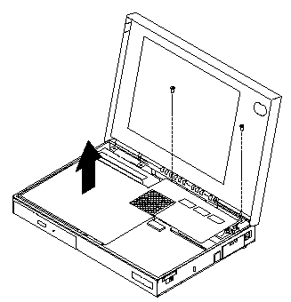
Attention
During removal and replacement procedures, make sure the Mylar cover does not interfere with the LCD Suspend Switch
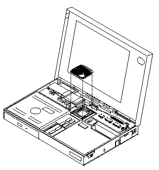
1060 Processor Card
Battery Pack (1020)
Keyboard (1050)
Mylar Cover (1055)
1065 LCD Inverter Card
Battery Pack (1020)
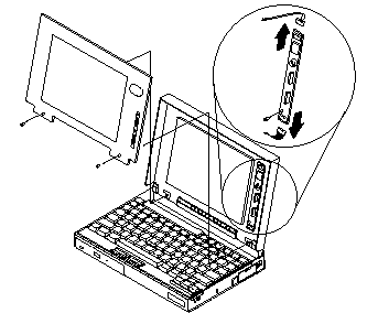
Note
Screws shown above are 8mm Long
1068 LCD Panel
Battery Pack (1020)
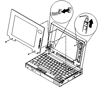
Note
Screws shown above are 8mm long.
1070 LCD Assembly
Battery Pack (1020)
Keyboard (1050)
Mylar Cover (1055)
Attention
Make note of the location and placement of ground points and tape. Replace tape to its original position.
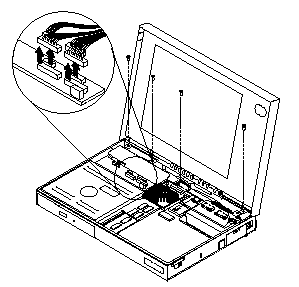
Note
Screws shown above are 6mm long
Note
Screws shown above are 8mm long
1080 Sound Card
Battery Pack (1020)
Keyboard (1050)
Mylar cover (1055)
LCD Assembly (1070)
Attention
During replacement, make sure the microphone (A), speaker (B) and sound card (C) cable connections are correct.
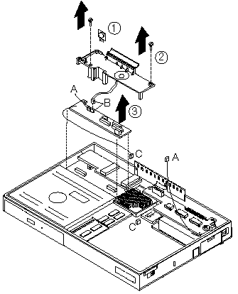
Note
Screws shown above are 6mm long.
1090 CD-ROM Drive
Battery Pack (1020)
Keyboard (1050)
LCD Assembly (1070)
Sound Card (1080)
Attention
During replacement, make sure that all connectors are properly aligned and seated.
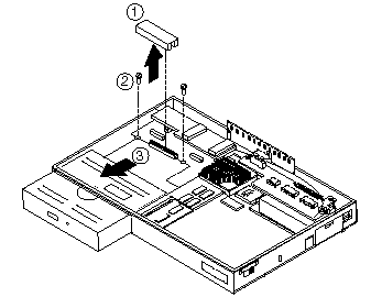
Note
screws shown above are 6mm long
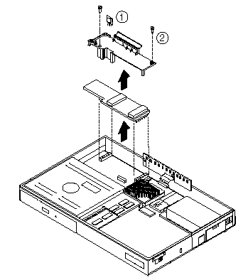
1100 Diskette Drive
Battery Pack (1020)
Keyboard (1050)
Mylar Cover (1055)
LCD Assembly (1070)
Sound Card (1080)
Attention
During replacement, make sure that all connectors are properly aligned and seated.

Note
Screws shown above are 6mm long
DC/DC Card
Battery Pack (1020)
Keyboard (1050)
Mylar Cover (1055)
LCD Assembly (1070)
Sound Card (1080)
Attention
During replacement, make sure the DC/DC Card connectors are properly aligned with the system board and fully seated.
Note
Screws shown above are 6mm long.
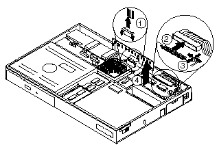
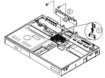
1020 Keyboar Card
Battery Pack (1020)
Keyboard (1050)
Mylar Cover (1055)
LCD Assembly (1070)
1. Disconnect all attached cable connectors.
2. Release the locking tab at the right rear of the keyboard card.
3. Remove the keyboard card.
1030 LED/IR Board
Battery Pack (1020)
Keyboard (1050)
Mylar Cover (1055)
LCD Assembly (1070)
Note
Screws shown above are 5mm long
|
Search Keywords |
| |
|
Hint Category |
Hardware Maintenance Information | |
|
Date Created |
16-03-98 | |
|
Last Updated |
19-08-98 | |
|
Revision Date |
18-08-99 | |
|
Brand |
IBM ThinkPad | |
|
Product Family |
ThinkPad 365C/CS, ThinkPad 365CD/CSD, ThinkPad 365E/ED | |
|
Machine Type |
2625 | |
|
Model |
Various | |
|
TypeModel |
| |
|
Retain Tip (if applicable) |
| |
|
Reverse Doclinks |