
|
57.081 bytes |
Product Information |
Document ID: MCGN-45WLLV |
Netfinity 5500 M20 - External options, connecting external SCSI devices and Input/Output ports and connectors
Applicable to: World-Wide
External Options
|
Note
|
For information about the maximum length of SCSI cable between the terminated ends of the cable, see ANSI SCSI Standards:
Setting SCSI IDs for external devices: Each SCSI device that is connected to a SCSI controller must have a unique SCSI ID, so that the SCSI controller can identify the devices and ensure that different devices do not attempt to transfer data at the same time. SCSI devices that are connected to different SCSI controllers can have duplicate SCSI IDs. See "SCSI IDs" and refer to the instructions that come with the SCSI devices for more information about setting a SCSI ID.
Installation Procedure: To attach an external device:
1. Turn off the server and all attached devices.
2. Follow the instructions that come with the option to prepare it for installation and to connect it to the server.
Input/Output Ports and Connectors: The input/output (I/O) connectors are for attaching external devices, such as printers, keyboards, and displays, to your server. The I/O connectors on your server include:
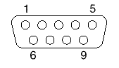
The following table shows the pin-number assignments for the serial-port connectors.
Table 3. Serial Port Pin-Number Assignments
|
Pin |
Signal |
Pin |
Signal |
|
1 |
Data carrier detect |
6 |
Data set ready |
|
2 |
Receive data |
7 |
Request to send |
|
3 |
Transmit data |
8 |
Clear to send |
|
4 |
Data terminal ready |
9 |
Ring indicator |
|
5 |
Signal ground |
When you turn on your server, the POST routine assigns the serial ports to specific communication port addresses.
Some application programs use only certain ports, and some modems are designed for use only at certain communication port addresses. You might need to use the Configuration/Setup Utility program to change communication port address assignments to resolve conflicts.
Management Port C: The server has a dedicated system-management I/O port. This port can be used to attach a modem that is dedicated to communication with the Netfinity Advanced System Management Processor.
The connector on the back of the server and the pin-number assignments are the same as for the serial ports.
Parallel Port: The parallel port usually is used to communicate with printers, and transfers data one byte at a time. The parallel port has a 25-pin, female D-shell connector on the back of the server. It support three standard IEEE 1284 modes of operation: Standard Parallel Port (SPP), Enhanced Parallel Port (EPP), and Extended Capability Port (ECP). (See "Input/output connectors and expansion slots" for the location of the connector.)
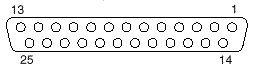
The following table shows the pin-number assignments for the parallel-port connector.
Table 4. Parallel port pin-number assignments
|
Pin |
I/O |
SPP/ECP Signal |
EPP Signal |
|
1 |
O |
-STROBE |
-WRITE |
|
2 |
I/O |
Data 0 |
Data 0 |
|
3 |
I/O |
Data 1 |
Data 1 |
|
4 |
I/O |
Data 2 |
Data 2 |
|
5 |
I/O |
Data 3 |
Data 3 |
|
6 |
I/O |
Data 4 |
Data 4 |
|
7 |
I/O |
Data 5 |
Data 5 |
|
8 |
I/O |
Data 6 |
Data 6 |
|
9 |
I/O |
Data 7 |
Data 7 |
|
10 |
I |
-ACK |
-ACK |
|
11 |
I |
BUSY |
-WAIT |
|
12 |
I |
PE (paper end) |
PE (paper end) |
|
13 |
I |
SLCT (select) |
SLCT (select) |
|
14 |
O |
-AUTO FD (feed) |
-DSTRB |
|
15 |
I |
-ERROR |
-ERROR |
|
16 |
O |
-INIT |
-INIT |
|
17 |
O |
-SLCT IN |
-ASTRB |
|
18 |
- |
Ground |
Ground |
|
19 |
- |
Ground |
Ground |
|
20 |
- |
Ground |
Ground |
|
21 |
- |
Ground |
Ground |
|
22 |
- |
Ground |
Ground |
|
23 |
- |
Ground |
Ground |
|
24 |
- |
Ground |
Ground |
|
25 |
- |
Ground |
Ground |
When you turn on your server, the POST routine assigns the parallel port a specific port address. You can change the parallel-port assignment by using the Configuration/Setup Utility program.
Video Port: The system board in your server has one SVGA video port. This port is used to attach a video monitor. The video port has a 15-pin analog connector on the back of the server. (See "Input/output connectors and expansion slots" for the location of the connector.)
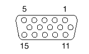
The following table shows the pin-number assignments for the video connector.
Table 5. Video port pin-number assignments
|
Pin |
Signal |
|
1 |
Red |
|
2 |
Green or monochrome |
|
3 |
Blue |
|
4 |
Monitor ID bit 2 |
|
5 |
Ground |
|
6 |
Ground |
|
7 |
Ground |
|
8 |
Ground |
|
9 |
+5 V dc |
|
10 |
Ground |
|
11 |
Monitor ID bit 0 |
|
12 |
DDC SDA |
|
13 |
Horizontal synchronization (Hsync) |
|
14 |
Vertical synchronization (Vsync) |
|
15 |
DDC SDL |
Keyboard and auxiliary-device ports: The system board has one keyboard port and one auxiliary-device port that supports a mouse or other pointing device. (See "Input/output connectors and expansion slots" for the locations of the connectors.)
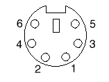
The following table shows the pin-number assignments for the connectors used by the keyboard and auxiliary-device ports.
Table 6. Keyboard and auxiliary-device port pin-number assignments
|
Pin |
Signal |
|
1 |
Data |
|
2 |
Not connected |
|
3 |
Ground |
|
4 |
+5 V dc |
|
5 |
Clock |
|
6 |
Not connected |
SCSI port: Your server comes with a RAID controller on the system board, which provides two independent SCSI channels. A 16-bit (wide) SCSI cable connects the hot-swap backplane to one channel of the integrated RAID SCSI controller. Another SCSI cable connects the other channel of the controller to the SCSI connector on the rear of the server.
To attach an external SCSI device to your server, connect an external SCSI cable from the SCSI device to the SCSI connector on the back of the server. Ensure that the last device on the external SCSI cable is terminated. Table 7 shows the pin-number assignments for the 68-pin SCSI connectors.
Table 7. 68-pin SCSI port connector pin-number assignments
|
Pin |
Signal |
Pin |
Signal |
|
1 |
Ground |
35 |
Data 12 |
|
2 |
Ground |
36 |
Data 13 |
|
3 |
Ground |
37 |
Data 14 |
|
4 |
Ground |
38 |
Data 15 |
|
5 |
Ground |
39 |
Data P1 |
|
6 |
Ground |
40 |
Data 0 |
|
7 |
Ground |
41 |
Data 1 |
|
8 |
Ground |
42 |
Data 2 |
|
9 |
Ground |
43 |
Data 3 |
|
10 |
Ground |
44 |
Data 4 |
|
11 |
Ground |
45 |
Data 5 |
|
12 |
Ground |
46 |
Data 6 |
|
13 |
Ground |
47 |
Data 7 |
|
14 |
Ground |
48 |
Data P0 |
|
15 |
Ground |
49 |
Reserved |
|
16 |
Ground |
50 |
-PRSN |
|
17 |
Terminal power |
51 |
Terminal power |
|
18 |
Terminal power |
52 |
Terminal power |
|
19 |
Reserved |
53 |
Reserved |
|
20 |
Ground |
54 |
Ground |
|
21 |
Ground |
55 |
-Attention |
|
22 |
Ground |
56 |
Ground |
|
23 |
Ground |
57 |
-Busy |
|
24 |
Ground |
58 |
-Acknowledge |
|
25 |
Not connected |
59 |
-Reset |
|
26 |
Ground |
60 |
-Message |
|
27 |
Ground |
61 |
-Select |
|
28 |
Ground |
62 |
-Control/Data |
|
29 |
Ground |
63 |
-Request |
|
30 |
Ground |
64 |
-Input/Output |
|
31 |
Ground |
65 |
Data 8 |
|
32 |
Ground |
66 |
Data 9 |
|
33 |
Ground |
67 |
Data 10 |
|
34 |
Ground |
68 |
Data 11 |
Ethernet Port: The system board in your Netfinity 5500-M10 contains an Ethernet controller. The controller has an external RJ-45 connector on the rear of the server that is used with a category 3, 4, or 5 unshielded twisted-pair (UTP) cable. The connector enables an Ethernet network to attach to the internal transceiver in your server.
|
Note |
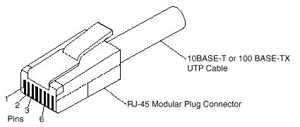
Table 8. Ethernet connector pin-number assignments
|
Pin |
Signal |
Pin |
Signal |
|
1 |
Transmit data+ |
5 |
Reserved |
|
2 |
Transmit data- |
6 |
Receive data- |
|
3 |
Receive data+ |
7 |
Reserved |
|
4 |
Reserved |
8 |
Reserved |
Universal serial bus ports: The system board in the Netfinity 5500 M20 contains two universal serial bus (USB) ports. Each USB port has an external connector on the rear on the server for attaching devices that previously used serial, parallel, keyboard, mouse, and game ports.
USB is an emerging serial interface standard for telephony and multimedia devices. USB technology uses Plug and Play to determine what device is attached to the connector. Each USB device is accessed by a unique USB address. A device called a hub is used to convert the USB port into multiple attachment points. A hub has multiple ports where peripherals can be attached. USB provides 12 megabits-per-second (Mbps) bandwidth with a maximum of 63 peripherals and a maximum signal distance of five meters (16 ft.) per segment.
Note
If more than one USB device is to be attached, then the device must be connected to a hub.
Table 9 shows the pin-number assignments for the USB connectors.
Table 9. USB connector pin-number assignments
|
Pin |
Signal |
|
1 |
VCC |
|
2 |
-Data |
|
3 |
+Data |
|
4 |
Ground |
RS-485 port: The system board has an RS-485 port that can be used by the Advanced System Management Processors of several servers mounted in a rack enclosure to communicate with each other in half-duplex mode.
Table 10 shows the pin-number assignments for the RS-485 connector.
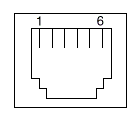
Table 10. RS-485 port pin-number assignments
|
Pin |
Signal |
|
1 |
+5 V dc |
|
2 |
+Data (tied to pin 4) |
|
3 |
-Data (tied to pin 5) |
|
4 |
+Data (tied to pin 2) |
|
5 |
-Data (tied to pin 3) |
|
6 |
Ground |
|
Search Keywords |
| |
|
Document Category |
Diagrams | |
|
Date Created |
12-03-99 | |
|
Last Updated |
21-05-99 | |
|
Revision Date |
16-03-2000 | |
|
Brand |
IBM PC Server | |
|
Product Family |
Netfinity 5500 M20 | |
|
Machine Type |
8662 | |
|
Model |
ALL | |
|
TypeModel |
| |
|
Retain Tip (if applicable) |
| |
|
Reverse Doclinks |