|
88.399 bytes |
Product Information |
Document ID: DDSE-43TRHV |
Netfinity 3500 - Completing the Installation
Applicable to: World-Wide
Completing the Installation
|
Note
Complete all the installation procedures for the internal options that you have chosen to install. |
1. Ensure that all components have been reassembled correctly and that no tools or loose screws are left inside the server.
2. Clear any cables that might impede the replacement of the cover.
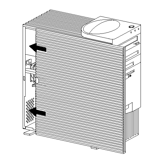
3. Install the side cover:
a. Align the top and bottom cover tabs with the corresponding notches on the frame of the server.
b. Slide the side cover to the rear, as shown in the following illustration. Make sure that the cover is latched into position.

4. Lock the side cover.
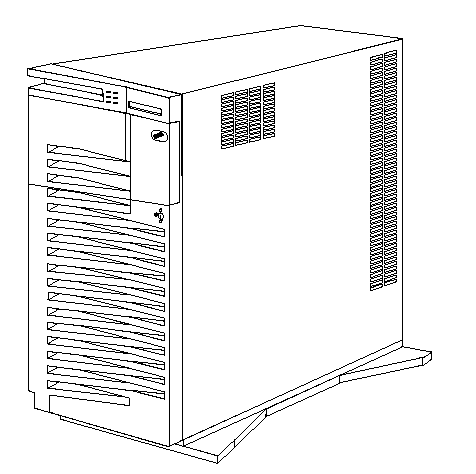
You can use the cover lock and keys to secure the outside cover.
|
Attention
In the United Kingdom, by law, the telephone cable must be connected after the power cord. |
5. Reconnect the cables to the back of the server; then, plug the power cords into properly grounded electrical outlets.
6. If a modem or fax machine is attached to the server, and you are not in the United Kingdom, reconnect the telephone line to the wall outlet and the server, and plug the power cords into properly grounded electrical outlets.
If you are in the United Kingdom, plug in the power cords first; then, connect the telephone line to the wall outlet and the server.
7. Power-on the server and all attached devices.
|
Attention
To allow for air circulation, be sure to maintain the following minimum clearances around the server:
102 mm (4 in.) in the front
127 mm (5 in.) in the rear
51 mm (2 in.) on the left and right sides |
8. When you have completed installing the covers and cables, go to "Server Configuration" on page 46.
Connecting External Options
To connect external options (SCSI drives and storage enclosures, printers, modems, and other serial and parallel devices), refer to the documentation that comes with the options.
The following information supplements the instructions that come with the external option. Use the instructions that come with the option to prepare it for installation.
Adding a Hot-Swap Storage Expansion Enclosure:
The IBM Hot-Swap Storage Expansion Enclosure is one of several SCSI storage enclosures that you can attach to the server. You can connect the storage enclosure to the external SCSI connector on a separately installed SCSI adapter.

Adding External SCSI Devices: The internal SCSI connector provides support for SCSI devices installed inside the server. The external SCSI connector provides support for external SCSI devices. The UltraSCSI controller on the system board can support a maximum of 15 devices.
|
Notes
If you plan to install both internal and external SCSI devices, you must follow the instructions given in "Internal Drives" on page 65 in addition to the instructions in this section. Read "Internal Drives" ; then, return here.
For additional information about SCSI configurations supported, see http://www.pc.ibm.com/us/server/
The server comes with a wide (16-bit) SCSI cable that supports 16-bit devices. If you want to attach narrow (8-bit) devices to the server, a SCSI 68-pin to 50-Pin Converter must be purchased that will enable the connection of the
device to the cable that comes with the server. It is good practice not to exceed the following cable-length guidelines:
- If you connect one or more Fast SCSI devices to the UltraSCSI controller, do not exceed 3 meters (9.8 feet) total length for all cables (internal and external)
- If you only connect Fast SCSI devices to the UltraSCSI controller, do not exceed 6 meters (19.7 feet) total length for all cables.
- If you connect four or less UltraSCSI devices to the UltraSCSI controller, do not exceed 1 meter (3.3 feet) total length for all cables. |
|
Attention
In addition to cable length and the number of installed devices, you must consider other factors that limit the performance of the SCSI subsystem. For example, if you install UltraSCSI devices in an external expansion enclosure that is limited to Fast transfer rates, the transfer rate to the UltraSCSI devices must be limited to Fast transfer rates. You accomplish this by using the SCSISelect Utility program. See "SCSISelect Utility" on page 42 for additional information. |
If you plan to attach an external SCSI device, you must order an additional SCSI cable. That is, to use an external device with the Netfinity 3500 server, you must connect it to the external SCSI connector, using a SCSI cable. This SCSI cable must have the proper connector for the SCSI external connector on one end, and the proper connector for the external device on the other end.
Attaching External Options: To attach an external option:
1. Power-off the server and all attached devices.
2. Follow the instructions that come with the option and the information in this chapter to connect it to the server.
|
|
Search Keywords |
|
|
Document Category |
Configuration |
|
|
Date Created |
04-01-99 |
|
|
Last Updated |
21-05-99 |
|
|
Revision Date |
12-04-2000 |
|
Brand |
IBM PC Server |
|
Product Family |
Netfinity 3500 |
|
|
Machine Type |
8644 |
|
|
Model |
ALL |
|
|
TypeModel |
|
|
|
Retain Tip (if applicable) |
|
|
|
Reverse Doclinks
and Admin Purposes |
|


