
|
25.461 bytes |
Service Hints & Tips |
Document ID: DDSE-3QRMMM |
|
This document is provided to IBM and our Business Partners to help sell and/or service IBM products. It is not to be distributed beyond that audience or used for any other purpose. |
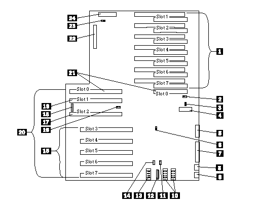
PC Server 720 - System board diagram / connections
Applicable to: World-Wide
System Board
1. PCI/Micro Channel connectors
2. PCI-speed-select jumper (J24, CE use only)
3. Power-on-features jumper (JMP4)
4. Serial connector
5. Video port
6. Password-write-enable jumper (JMP2)
7. Parallel port
8. Pointing-device port
9. Keyboard port
10. 3.3V power connector
11. Remote-update jumper (J25, CE use only)
12. Power connector
13. 5V power connector
14. Bank-select jumper (JMP5)
15. Processor board slots
16. Power-on-password jumper (JMP1)
17. Memory/processor slot
18. Fan connector
19. Memory card slot
20. Bus slots
21. Bridge card slot
22. Diskette-drive cable connector
23. Bad-CMOS jumper (J42)
24. Operator-panel cable connector

Note:
For default settings, refer to the label located inside the system.
|
Search Keywords |
| |
|
Hint Category |
Hardware Maintenance Information, Processors | |
|
Date Created |
26-08-96 | |
|
Last Updated |
22-01-99 | |
|
Revision Date |
29-09-99 | |
|
Brand |
IBM PC Server | |
|
Product Family |
PC Server 720 | |
|
Machine Type |
8642 | |
|
Model |
| |
|
TypeModel |
| |
|
Retain Tip (if applicable) |
| |
|
Reverse Doclinks |