
|
85.567 bytes |
Service Hints & Tips |
Document ID: GSMH-3DAEUK |
TP Dock I - Power Systems Checkout
Applicable to: World-Wide
Power Systems Checkout:
If the 'power goodó light is not on and the power supply fan is not turning, check the power cord for continuity and correct installation.
If the power cord is not the problem, either the power supply is defective, or another component is defective causing the power supply to shut off.
To verify that the power supply is operating correctly, do the following:
1. Power-off the computer and disconnect the Dock I power cord.
2. Remove all internal and external devices, and the computer from the Dock I.#
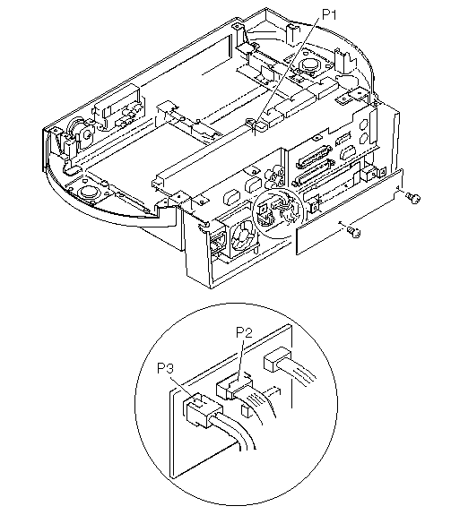
3. Remove power supply connector P3 from the I/O card and the SCSI power supply connector from the SCSI device.

4. Install jumpers between pins 1 and 2, and pins 3 and 4 of JP2 on the main board of the Dock I.

5. Connect the Dock I power cord.
6. Check the power supply voltages on connector P3 using Table 3 on page 9, then check that the fan is turning. If the voltage is not correct or the fan is not turning, replace the power supply.
7. Disconnect the Dock I power cord.
8. Remove the jumpers installed in Step 4.
9. Remove power supply connector P1 from the main board and P2 from the I/O card.
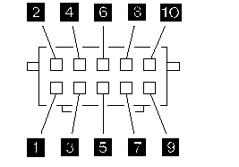
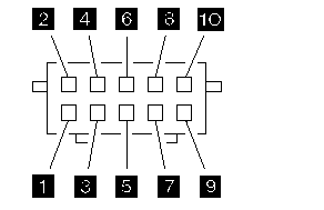
10. Install jumpers between pins 2 and 6, and pins 8 and 9 of connector P2 of the power supply.
11. Connect the Dock I power cord.
12. Check the power supply voltages on connectors P1, P2, and the SCSI power supply connector using Table 1 and Table 2 , then check that the fan is turning.
If any of the voltages are not correct, replace the power supply.
If all voltages are correct, the power supply is working correctly. Other Dock I parts can cause the power supply to shut off. Return to the procedure that sent you here and continue. (If you have completed that procedure, go to 'Undetermined Problemó)
Power Supply Connector P1:

Table 1. Power Supply Connector P1:
|
Pin |
Signal |
V dc Min. |
V dc Max. |
|
1, 2, 3 |
+5 volts |
+ 4.8 |
+ 5.25 |
|
4,5 |
Ground |
- |
- |
|
6 |
- 12 volts |
- 11.46 |
- 13.2 |
|
7 |
Ground |
- |
- |
|
8 |
+ 12 volts |
+ 11.46 |
+ 12.6 |
|
9 |
-5 volts |
- 4.53 |
- 5.5 |
|
10 |
Ground |
- |
- |
Power Supply Connector P2:

Table 2. Power Supply Connector P2:
|
Pin |
Signal |
V dc Min. |
V dc Max. |
|
1 |
Power on |
- |
- |
|
2 |
System on |
+ 4.0 |
+ 5.25 |
|
3 |
VCC |
- |
- |
|
4 |
Mode control |
- |
- |
|
5 |
+5 volts |
+ 4.8 |
+ 5.25 |
|
6,8 |
Ground |
- |
- |
|
7 |
+ 12 volts |
+ 11.46 |
+ 12.6 |
|
9 |
Docked |
- |
- |
|
10 |
NC |
- |
- |
Power Supply Connector P3:
Table 3. Power Supply Connector P3
|
Pin |
Signal |
V dc Min. |
V dc Max. |
|
1 |
CVCC |
+ 19 |
+ 21 |
|
2 |
Ground |
- |
- |
SCSI Power Supply Connector:
Table 4. SCSI Power Supply Connector

|
Pin |
Signal |
V dc Min. |
V dc Max. |
|
1 |
+ 12 volts |
+ 11.46 |
+ 12.6 |
|
2,3 |
Ground |
- |
- |
|
4 |
+5 volts |
+ 4.8 |
+ 5.25 |
|
Search Keywords |
| |
|
Hint Category |
Hardware Maintenance Information | |
|
Date Created |
13-01-97 | |
|
Last Updated |
27-08-98 | |
|
Revision Date |
21-08-99 | |
|
Brand |
IBM ThinkPad | |
|
Product Family |
ThinkPad Docking Stations | |
|
Machine Type |
3545 | |
|
Model |
001 | |
|
TypeModel |
| |
|
Retain Tip (if applicable) |
N/A | |
|
Reverse Doclinks |