
|
77.156 bytes |
Service Hints & Tips |
Document ID: GSMH-3EQEHG |
TP 365X/XD - 1120 CPU Card and System Board Card
Applicable to: World-Wide
1120 CPU Card and System Board Card:
Battery Pack (1020)
Insulator Sheet (1025)
Diskette Drive / CD-ROM Drive (1040)
Hard Disk Drive (1050)
Top Cover (1060)
Keyboard Unit (1070)
LCD Assembly (1080)
LCD Panel (1085)
Indicator Card (1090)
Volume Switch / Speaker (1100)
Keyboard Card (1110)
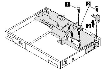
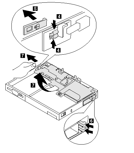
To remove the system board and CPU Card:

|
Step |
Screw Location (Quantity) |
Length |
|
1 |
CPU Card to System Board (1) |
M2 x 4 mm |
|
2 |
CPU Card to System Board (2) |
M2 x 5 mm |
Note:
Make sure you use the correct screws when replacing.
Note:
The system board fits exactly in place in the base cover. Align the system board carefully when removing or reinstalling. Do not force it. Be careful not to damage the input jacks on the left side of the computer or the PCMCIA slots on the right side of the computer.

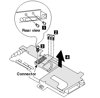
To remove the CPU card from the system board:

Be Careful:
When connecting the CPU card and the system board again, use the procedures exactly as shown in the figures. Make sure that the two CPU card connectors are connected properly. If these connectors are not properly connected, the computer will not work.
|
Step |
Screw Location (Quantity) |
Length |
|
1 |
System Board (2) |
M2 x 4 mm |
|
2 |
System Board (3) |
M2 x 4 mm |
|
3 |
System Board (1) |
M2 x 4 mm |
Note:
Make sure you use the correct screws when replacing.
|
Search Keywords |
| |
|
Hint Category |
Hardware Maintenance Information | |
|
Date Created |
28-02-97 | |
|
Last Updated |
19-08-98 | |
|
Revision Date |
18-08-99 | |
|
Brand |
IBM ThinkPad | |
|
Product Family |
ThinkPad 365X/XD | |
|
Machine Type |
2625 | |
|
Model |
Various | |
|
TypeModel |
| |
|
Retain Tip (if applicable) |
| |
|
Reverse Doclinks |