
|
90.241 bytes |
Service Hints & Tips |
Document ID: GSMH-3C7EU3 |
|
This document is provided to IBM and our Business Partners to help sell and/or service IBM products. It is not to be distributed beyond that audience or used for any other purpose. |
Laptop L40SX - FRU Removals And Replacements
Applicable to: World-Wide
FRU Removals and Replacements:
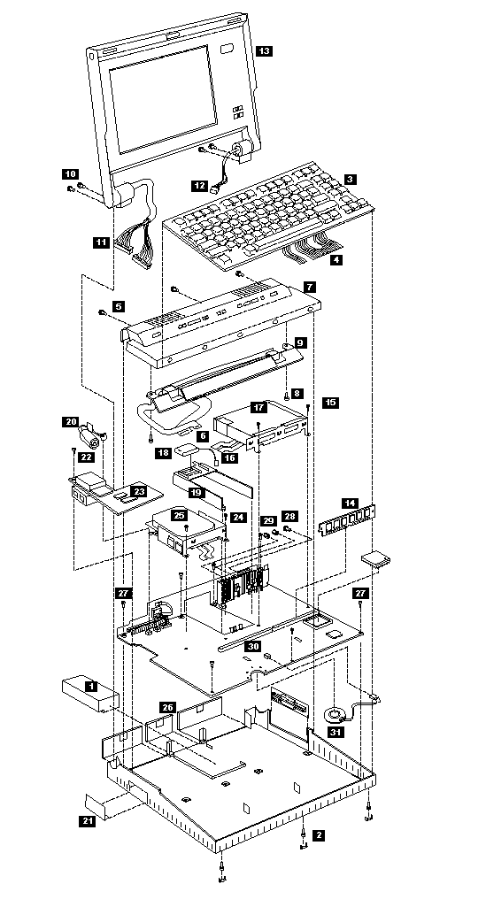
Follow the numerical sequence in the FRU removal sequence list and the exploded view to remove or disconnect parts in the correct order. The letters in parentheses in the list indicate screw types. See the -- 'Screw Size Chart' -- to match the letters to the correct screw type and size before replacing each screw.
Safety Notice 8:
Before removing any FRU, power-off the computer, unplug all power cords from electrical outlets, remove the battery pack, then disconnect any interconnecting cables.
Safety Notice 1:
Before the computer is powered-on after FRU replacement, make sure all screws, springs, or other small parts are in place and are not left loose inside the computer. Verify this by shaking the computer and listening for rattling sounds. Metallic parts or metal flakes can cause electrical shorts.
|
1 |
Battery Pack |
|
2 |
Three Screw Covers and Three Screws (C) |
|
3 |
Loosen Keyboard Assembly |
|
4 |
Two Ribbon Cables and Keyboard |
|
5 |
Three Top Cover Screws (C) (Inside right and left rear access doors along top edge) |
|
6 |
Two Status Display Ribbon Cables |
|
7 |
Top Cover |
|
8 |
Two Status Display Screws (F) |
|
9 |
Status Display Assembly (contains on/off and power saver switches) |
|
10 |
Four Hinge Screws (C) |
|
11 |
Left Hinge Cables |
|
12 |
Right Hinge Cables |
|
13 |
LCD Assembly |
|
14 |
Memory Modules |
|
15 |
Two Screws (F) |
|
16 |
Two Diskette Drive Ribbon Cables |
|
17 |
Diskette Drive and Drive Mounting Bracket |
|
18 |
Standby Battery |
|
19 |
Battery Shield |
|
20 |
Backup Battery |
|
21 |
Adapter Bezel |
|
22 |
One Screw (F) |
|
23 |
Serial/Modem Card |
|
24 |
Two Screws (F) |
|
25 |
Two Ribbon Cables and Hard Disk Drive |
|
26 |
External Adapter and Battery Doors |
|
27 |
Eight System Board Screws (F) |
|
28 |
One Screw (C) |
|
29 |
Two Threaded Hex Spacers |
|
30 |
System Board |
|
31 |
Speaker |
Model L40 Exploded View:

|
Search Keywords |
| |
|
Hint Category |
Hardware Maintenance Information | |
|
Date Created |
09-12-96 | |
|
Last Updated |
15-04-98 | |
|
Revision Date |
02-04-99 | |
|
Brand |
IBM ThinkPad | |
|
Product Family |
Laptop L40 | |
|
Machine Type |
8543 | |
|
Model |
Various | |
|
TypeModel |
| |
|
Retain Tip (if applicable) |
N/A | |
|
Reverse Doclinks |