
|
33.038 bytes |
Service Hints & Tips |
Document ID: DDSE-3R7JC9 |
|
This document is provided to IBM and our Business Partners to help sell and/or service IBM products. It is not to be distributed beyond that audience or used for any other purpose. |
Server Options - 3518 Power Supplies
Applicable to: World-Wide
Power Supplies:
Attention:
Always unplug the power cord and wait two minutes before replacing the power supply to give the power supply capacitors time to discharge.
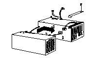
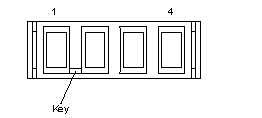
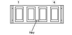
The expansion tower is shipped with a primary power supply. An additional or optional power supply can be added to the computer. Connectors are used to transfer the primary power supply voltages and signals from the primary power supply to the optional power supply. The following illustrations show how the two power supplies are connected.
Attention:
When replacing the primary power supply cover plate, rotate the plate 180 Degrees. (This will leave an opening for the primary power supply connector cable that connects to the optional power supply.) Failure to do so will cause the power supply connector cable to be crimped when the plate is replaced.

Note:
Tabs are located on the side of each power supply to secure them together.
Power Supply LED and Button:
The power-good LED and button are located on the side of the primary power supply button. The LED (when lit) indicates that the power supply is good.
If the LED fails to come on when the computer is powered-on, do the following:
While observing the LED on the power supply, press the power supply button. If the LED fails to light (while you are holding the button in), you may have a defective power supply. If the LED lights when the button is pressed, go to ¿Power Supply Shutdowns—.
Primary Power Supply Voltages:
If the voltages are correct and the power supply fan runs, the power supply is OK.
Connector P1

|
- Lead |
+Lead |
V dc |
V dc |
|
4 |
1 |
+ 4.8 |
+ 5.25 |
|
4 |
2 |
+ 4.8 |
+ 5.25 |

|
- Lead |
+Lead |
V dc |
V dc |
|
4 |
1 |
+ 3.3 |
+ 3.5 |
|
4 |
2 |
+ 3.3 |
+ 3.5 |
Connector P3

|
- Lead |
+Lead |
V dc |
V dc |
|
2 |
4 |
+ 11.52 |
+ 12.6 |
|
2 |
5 |
+ 11.52 |
+ 12.6 |
|
2 |
8 |
- 10.8 |
- 13.2 |
|
2 |
10 |
+ 4.8 |
+ 5.25 |

|
- Lead |
+Lead |
V dc |
V dc |
|
B |
A |
+ 4.8 |
+ 5.25 |
|
B |
D |
+ 11.52 |
+12.6 |
Optional Power Supply Drive Connector Voltages:
If the voltages are correct and the power supply fan runs, the power supply is OK.

|
- Lead |
+Lead |
V dc |
V dc |
|
B |
A |
+ 4.8 |
+ 5.25 |
|
B |
D |
+ 11.52 |
+12.6 |
Power Supply Shutdowns:
If the power supply shuts down, or appears to fail at power-on, you might have one of the following problems:
Too many devices are set to start instantly. See 'Setting the Motor-Start Jumper'. There are too many large-capacity devices installed (such as hard disk drives). The nominal operating current of the devices installed collectively exceeds the available current of the power supply. See the ¿Personal System/2 Installation Planning— guide (form number S41G-2927) for more information.
Also ensure that the fans operate when the machine is powered on.
Note:
Verify that the voltage-select switch (if applicable) is set for the correct voltage.
If the voltages are correct and the Symptom-to-FRU index does not solve the problem, go to 'Undetermined problems'
|
Search Keywords |
| |
|
Hint Category |
Hardware Maintenance Information | |
|
Date Created |
07-10-96 | |
|
Last Updated |
21-04-98 | |
|
Revision Date |
17-04-99 | |
|
Brand |
IBM PC Server | |
|
Product Family |
Rack/Storage Enclosures | |
|
Machine Type |
3518 | |
|
Model |
| |
|
TypeModel |
| |
|
Retain Tip (if applicable) |
N/A | |
|
Reverse Doclinks |