
|
53.927 bytes |
Parts Information |
Document ID: DDSE-44JQW4 |
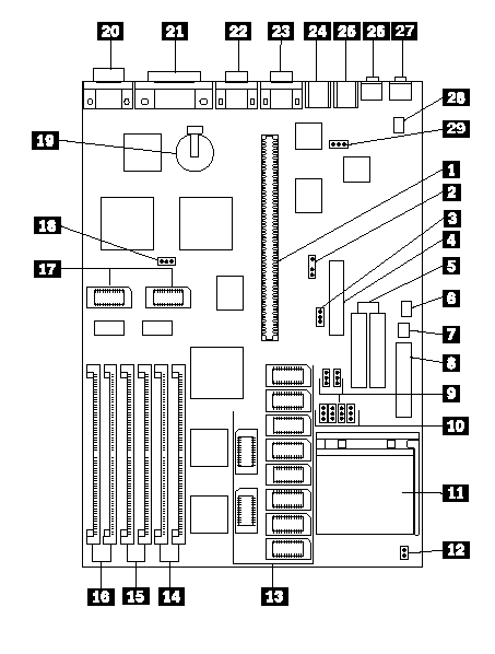
PC Server 310 - System Board Diagram
Applicable to: World-Wide
System Board

System Board (Continued)
1. Riser connector
2. MRD Modem Ring Detect jumper
3. WP Diskette drive write protect jumper
4. Diskette drive connector
5. Hard disk drive connectors
6. J38 On/Off Switch Power Supply Connector
7. J37 On/Off Switch Connector
8. Power supply connectors
9. J26, J27 Bus/CPU Speed (MHz)
10. 256KB/1MB Cache jumpers
11. Processor connector
12. J101 Bus/Core Ratio
13. Cache connectors
14. Memory connectors (Bank 2)
15. Memory connectors (Bank 1)
16. Memory connectors (Bank 3)
17. Video memory modules
18. PWD Power-on password jumper
19. Battery
20. Display connector
21. Parallel connector
22. Serial connector
23. Serial connector
24. Keyboard connector
25. Mouse connector
26. Audio (input jack)
27. Audio (output jack)
28. IDE CD-ROM Audio connector
29. J28 Mouse jumper
|
Search Keywords |
| |
|
Document Category |
System Boards | |
|
Date Created |
27-01-99 | |
|
Last Updated |
27-01-99 | |
|
Revision Date |
27-01-2000 | |
|
Brand |
IBM PC Server | |
|
Product Family |
PC Server 310 | |
|
Machine Type |
8639 | |
|
Model |
| |
|
TypeModel |
| |
|
Retain Tip (if applicable) |
| |
|
Reverse Doclinks |