

|
212.711 bytes |
Service Hints & Tips |
Document ID: GSMH-3EQGZW |
TP General - Common Devices Checkout
Applicable to: World-Wide
Common Devices Checkout:
External Diskette Drive Test:
Use the following procedure to isolate the diskette problem to a controller, drive or diskette. A scratch, write-enabled 2HD diskette is required.
1. Select the icon FDD on the TEST MENU. By doing this, the controller test and the drive read/write test run. If the controller test detects an error, FRU code 10 appears. In this case, replace the system board.
2. If the controller test run without errors, follow the instructions on the screen and insert a scratch diskette.
3. If the drive test detects an error, FRU code 50 appears. If the diskette media are known to be good, replace the drive or the drive cable.
External Display Self-Test:
If the display problem occurs only when using an external display, use the following instructions to correct the problem.
Note:
Before you replace a display, check the following list to see if it is connected correctly.
- 8506 and 8508 displays must be connected to an Image Adapter/A or an Image-I Adapter/A.
- 63XX and 85XX systems support either 63XX or 85XX displays.
- 85XX systems with an XGA-2 adapter support 95XX displays.
- 95XX systems support either 63XX, 85XX, or 95XX displays.
- ThinkPad models support either 85XX or 95XX displays.
If the screen is rolling, replace the display assembly. If that does not correct the problem, replace FRUs in the following order until the problem goes away:
1. Video card
2. Display adapter (any type)
3. System board
4. Bus adapter (if used)
If the screen is not rolling, run the display self-test as follows:
1. Power-off the computer and display.
2. Disconnect the display signal cable.
3. Power-on the display.
4. Set the contrast to its maximum position.
5. Set the brightness control to the center detent position.
Check for the following conditions:
You should be able to vary the screen intensity by adjusting the contrast and brightness controls. The screen should be white or light gray, with a black margin (test margin) on the screen.
Note:
The location of the test margin varies with the type of display. The test margin might be on the top, bottom, or one or both sides.
If you do not see a test margin on the screen, replace the display. If there is a test margin on the screen, replace the system board.
Note:
On ThinkPad Models 700, 700C, 720C, 720C, do the following:
1. Video card
2. System board
External Keyboard/Auxiliary Input Device Checkout:
The following auxiliary input devices may be available for IBM ThinkPad models.
- Numeric keypad
- Mouse (PS/2 compatible)
- External keyboard (with Keyboard/Miniature Mouse cable)
If you suspect a problem with any of the auxiliary input devices (listed above), replace the device. If the problem is not corrected, replace the following FRUs one at a time to correct the problem.
- Keyboard control card
- System board
If the computer receives an incorrect keyboard response, remove other external devices, check the keyboard connections, and recheck the keyboard responses. If the problem remains, replace the following FRUs one at a time to correct the problem.
- Keyboard
- Keyboard control card
- System board
If a 000 30100 error message appears, power-off the computer and the external devices. Then power-on the computer before you power-on the external devices.
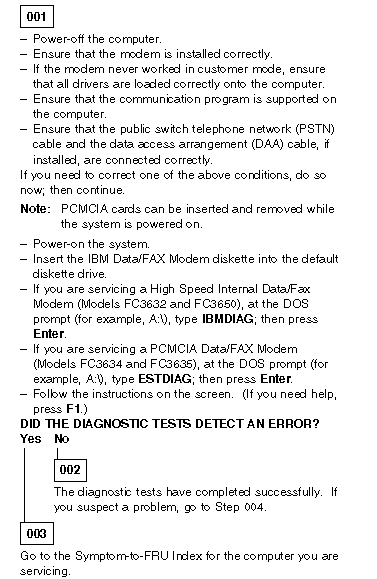
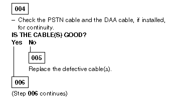
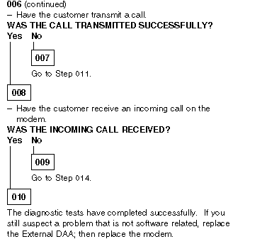
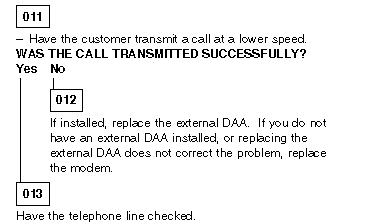
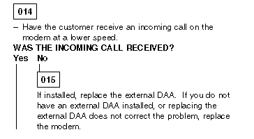
Fax/Modem Checkout:

Printer Checkout:
1. Make sure the printer is correctly connected and is powered-on.
2. Run the printer self-test.
If the printer self-test does not run correctly, the problem is in the printer. Refer to the printer service manual.
If the printer self-test runs correctly, do the following.
1. Verify the port settings in configuration.
2. Install a wrap plug on the port (indicated in configuration) and run the advanced diagnostic tests.
3. If the advanced diagnostic tests (with the wrap plug installed) do not detect a failure, replace the printer cable. If the problem is not corrected, replace the system board.
Port Replicator Checkout:
Use the following procedure to isolate a port replicator problem. A port replicator attaches to the system expansion connector at the rear of the computer.
1. Power-off the computer.
2. Remove the failing devices from the replicator.
3. Unplug the AC adapter from the replicator, if attached.
4. Remove the port replicator from the computer.
5. Reconnect the failing device directly to the computer. (If another device occupies the connector, remove it first.)
6. Go to General Checkout and follow that procedure.
7. If the advanced diagnostic device test does not find an error, suspect a problem with the port replicator or the system expansion bus.
8. Power-off the computer and reconnect the port replicator.
9. Power-on the computer and run the following advanced diagnostic tests:
Serial port test with the wrap plug installed on the replicator.
Parallel port test with the wrap plug installed on the replicator.
PCMCIA-2 test with the PC test card installed.
FDD-2 (FDD-1 if no drive is installed in the computer) drive test on the failing device.
10. If diagnostic errors appear, replace the replicator or diskette drive attachment unit.
If the problem remains after the replacement, replace the system board.
11. If power problems appear only when using the replicator, replace the replicator.
If power shut downs occur intermittently when using PCMCIA-2 devices via a port replicator, suspect an over-current problem. Some PCMCIA devices use more power; if the maximum usage of each device occurs simultaneously, the total current will exceed the limit, thereby causing a power shut down. Isolate this problem by removing one of the devices, and use the computer under the same condition, and see whether a power shut down occurs. Do this procedure for all devices then determine the cause. Customer purchase of the larger AC adapter (50W, optional) is recommended, if it is not yet in use.
TrackPoint Checkout:
If the TrackPoint does not work, check the configuration. If the configuration of the TrackPoint is set to Disabled or Off, change it to Enable or On. If the problem remains, continue.
Note:
TrackPoint automatically compensates to adjust the pointer sensor. This causes the pointer to move slightly on the screen and then stop. Pointer movement might occur when a slight, steady pressure is applied to the TrackPoint pointer when the computer is powered-on or running, or when exceeded temperature range requires re-adjustment.
If the cursor floats or moves erratically, power-off and disconnect the mouse. Power-on the computer. If the problem goes away, replace the mouse. If the problem remains, replace the keyboard.
For click button or pointing stick problems:
1. Go to the Easy-Setup screen.
2. Select an item with the pointing stick.
3. Press either left or right click button.
4. Verify that both buttons work correctly.
If the pointing stick or the click button does not work, do the following.
1. Reseat the keyboard cables.
2. Replace the keyboard.
3. Replace the interposer card (355x, 360x, 750x, 755x).
4. Replace keyboard control card (720).
5. Replace the system board.
TV Tuner:
The TV Tuner Pack (hereafter called TV Tuner) is an option for watching TV programs or videos on the IBM TFT color notebook computer. The computer changes to TV reception when the removable diskette drive is replaced with the TV Tuner.
The TV screen and normal computer display are easily switched by using the Hot key on the front panel of the TV Tuner.
Identifying Names and Functions:
The following figure and table show the names and functions of each part of the TV Tuner.
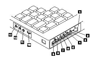
|
Icons |
Functions |
|
1 Front Panel |
Used to change the TV channels, switch TV mode to computer mode, and operate most functions of the TV Tuner. |
|
2 Headphone Jack |
Connects the headphones. |
|
3 Power Indicator |
Shows the TV Tuner is powered on. |
|
4 Switch |
Power Powered on and off the TV Tuner. |
|
5 Hot Key |
Switches between the TV screen and computer screen. |
|
6 Up Switch |
Increases the value such as the channel number. |
|
7 Down Switch |
Decreases the value such as the channel number. |
|
8 Function Key |
Enters the mode to change the value of each function, such as TV channel or color contrast. (See "Using the Function Key".) |
|
9 TV/EXT Switch |
Switches the TV mode or external video mode. |
|
10 Volume Knob |
Controls the speaker volume. |
|
11 Audio-In Jack |
Connects the audio-in connector of the AV cable. |
|
12 Video-In Jack |
Connects video-in connector of the AV cable. |
|
13 RF Connector |
Connects the active antenna unit or antenna cable. |
Using the Front Panel:
The following table shows how to operate all functions of the TV Tuner with the controls on the front panel.
|
Key |
Function |
|
Power |
Turns on the TV Tuner. This key is used only when the computer is turned on. |
|
Hot Key |
Switches computer display and TV screen. |
|
Up |
Increases the value of parameters, Channel Number, Color, Tint, Brightness, Contrast, Auto Tuning Sensitivity, On-screen Message Selection. |
|
Down |
Decreases the value of parameters, Channel Number, Color, Tint, Brightness, Contrast, Auto Tuning Sensitivity, On-screen Message Selection. |
|
Function |
Selects a function mode to adjust each function parameter. |
|
TV/Ext |
Switches the displayed video source between the receiving TV broadcast program and external devices such as VCR, video camera recorder, laser disk, and so on. |
Using the Function Key:
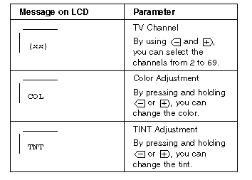
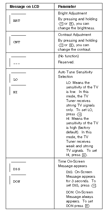
Each time you press the Function key (FN ), one of the following messages (called On-Screen Message ) appears at the top left corner of the LCD. The changed values are automatically saved when you return to the "TV Channel" On-Screen message. The values are not saved when you power-off the TV Tuner without returning to this message.
Power-on the TV Tuner:
Use the ThinkPad Features program or PS2.EXE. to power-on the TV Tuner; then power-on the internal device in the diskette drive compartment. If power for the internal device is turned off when the TV Tuner is set up, nothing appears on the LCD display. Turn on power for the TV Tuner again.
If you are using DOS, do one of the following:
- Power-on the computer and type PS2 from the command prompt to start the ThinkPad Features program. Select Set Power Features from the ThinkPad Features menu; then put a check mark at Internal Serial Port (or Diskette Drive Compartment ) under the Power for devices. If you need help, press F1 to display the help menu.
- Type PS2 MODEM ON (or PS2 DDC ON) from the command prompt; press the Enter key to set the power ON.
If you are using OS/2* or Microsoft Windows**, do the following:
1. Power-on the computer and start the ThinkPad Features program.
2. Select the Power icon; then move the pointer to Internal Serial Port (or Diskette Drive Compartment ) under the Power for devices and click the button to check mark it.
3. Press the OK button.
Troubleshooting:
The following table shows what to do to solve problems when the TV Tuner does not work correctly.
|
Problem |
Probable Cause |
|
The TV Tuner does not operate. |
Computer is not powered on. - Computer is in suspend mode. - The TV Tuner is not set up correctly. |
|
No color. |
The program is not in color. |
|
Snow and noise only. |
Switch the TV/EXT |
|
Pictures are out of shape, or have double images. |
For TV: |
|
Dotted lines or stripes. |
Usually caused by interference from neon signs, hair dryers, and so on. Move the computer to avoid the interference. |
|
Picture control are not saved. |
Do not power-off the TV Tuner when adjusting functions such as picture control, color, tint, brightness, or contrast. |
|
Channel number is always displayed or is not displayed. |
Select your favorite mode for the on-screen message. |
|
Search Keywords |
| |
|
Hint Category |
Hardware Maintenance Information | |
|
Date Created |
28-02-97 | |
|
Last Updated |
19-08-98 | |
|
Revision Date |
18-08-99 | |
|
Brand |
IBM ThinkPad | |
|
Product Family |
ThinkPads General | |
|
Machine Type |
Various | |
|
Model |
Various | |
|
TypeModel |
| |
|
Retain Tip (if applicable) |
| |
|
Reverse Doclinks |