
|
241.055 bytes |
Service Hints & Tips |
Document ID: GSMH-3C8HRB |
|
This document is provided to IBM and our Business Partners to help sell and/or service IBM products. It is not to be distributed beyond that audience or used for any other purpose. |
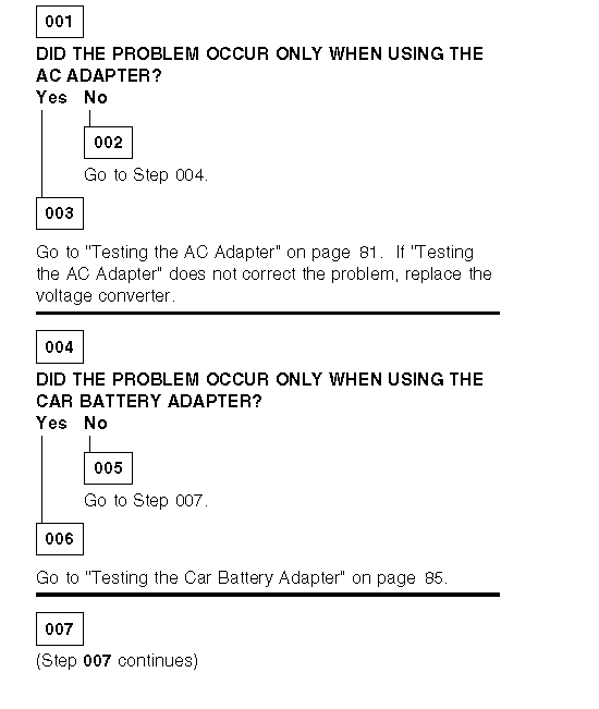
TP General - N51 Power System Checkout
Applicable to: World-Wide
Power Systems Checkout:
Note:
One or all of the batteries can discharge if there is a short circuit in the computer.
1. Replace the failing FRU if the power supply problem is caused by a short circuit.
2. Determine if one (or all) of the batteries have become discharged. Replace a discharged battery with a known-good spare.
The test procedures for each power supply are found on the following pages.
- ┐Testing the AC AdapterŚ.
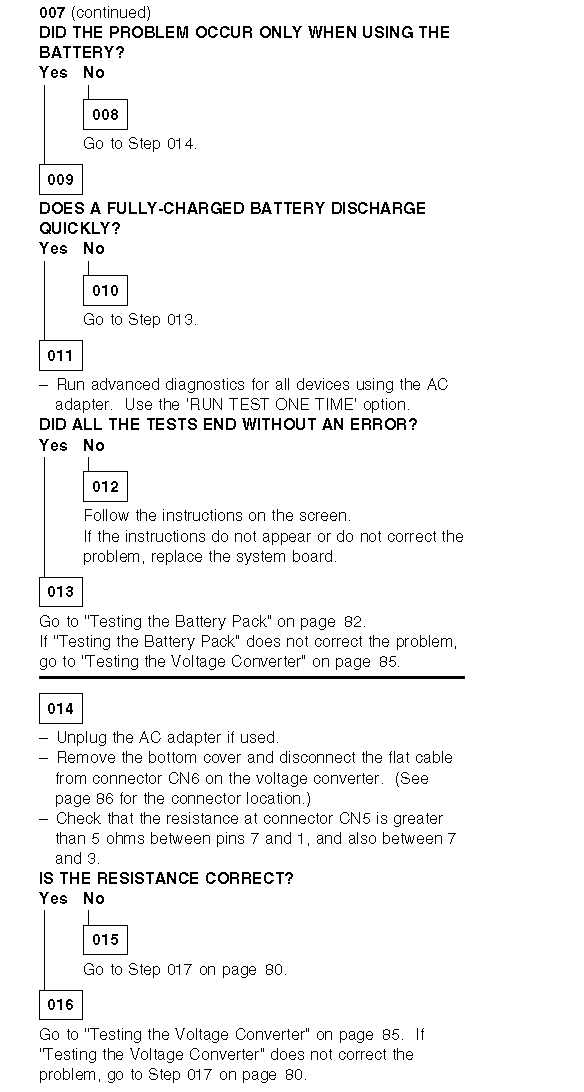
- ┐Testing the Battery PackŚ.
- ┐Testing the Backup BatteryŚ.
- ┐Testing the Standby BatteryŚ.
- ┐Testing the Quick ChargerŚ.
- ┐Testing the Car Battery AdapterŚ.
- ┐Testing the Voltage ConverterŚ.
None of the above? Follow the steps below.
Testing the AC Adapter:
If the Power-On indicator is not on, check the power cord of the AC adapter for proper installation and continuity.
1. If any noise can be heard from the AC adapter when it is plugged into line voltage, replace the AC adapter with a new one.
If no noise can be heard from the adapter, go to Step 3.
2. If the noise still comes from the new AC adapter, suspect the computer. Replace the AC adapter with the original one, then go to the next step. If no noise comes from the new adapter, the original adapter has the problem.
3. Unplug the AC adapter cable from the computer and measure the output voltage at the plug of the AC adapter cable.
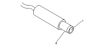
|
Pin |
Voltage (V dc) |
|
1 |
+ 19.0 to+ 21.0 |
|
2 |
Ground |
If the voltage is not correct:
1. Unplug the AC adapter from the ac power outlet and leave it for a few minutes.
2. Plug the AC adapter into the ac outlet.
3. Measure the output voltage of the AC adapter.
4. If the voltage is still not correct, replace the AC adapter.
If the voltage is OK, plug the cable into the computer and try the failing operation again.
If the problem still remains, replace the voltage converter. If the problem disappeared, suspect the installation and continuity of the AC adapter cable.
Testing the Battery Pack:
1. Place the computer bottom-side up.
2. Remove the battery pack and measure the voltage at the battery terminals between 1 (+ ) and 3 (- ).
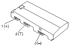
|
Pin |
Voltage (V dc) |
|
1 |
+ 8.5 to+ 18.0 |
|
2 |
Thermal Detection |
|
3 |
Ground |
If the voltage is less than+ 8.5 V dc, the battery pack is discharged or defective. If the voltage is more than+ 8.5 V dc, go to the next step.
3. Using a low-power ohm meter, measure the resistance at the battery terminals between 2 (T) and 3 (- ). The resistance must be 4 kilohms to 30 kilohms. If the resistance is out of range, replace the battery pack.
4. Remove the bottom cover and set the battery pack in place without connecting any external power devices.
5. Measure the voltage at the connector between terminals 1 (+ ) and 3 (- ) on the voltage converter and note the voltage.

6. Using the AC adapter, apply external power to the computer.
Warning:
Be careful not to cause a short circuit while doing the following steps. The charging circuit is active even if the computer power switch is set to off.
7. Measure the voltage again between terminals 1 (+ ) and 3 (- ).
If the voltage is not greater than that measured in Step 5, replace the AC adapter, then go to the next step. If the voltage is greater than that measured in Step 5, the battery pack is good. Repeat Steps 6 and 7 using a new AC adapter. If the voltage is still not greater than that measured in Step 5, replace the voltage converter.
Testing the Backup Battery:
1. Place the computer bottom-side up.
2. Remove the bottom cover.
3. Disconnect the battery connector from the voltage converter.
4. Measure the voltage of the backup battery.
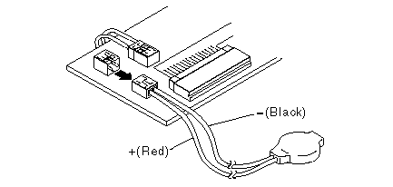
|
Wire |
Voltage (V dc) |
|
Red |
+ 2.5 to+ 3.7 |
|
Black |
Ground |
If the voltage is correct, replace the system board. If it is not, the backup battery is discharged by a short circuit or is defective.
Testing the Standby Battery:
1. Place the computer bottom-side up.
2. Remove the battery pack from the computer and remove the bottom cover.
3. Disconnect the battery connector from the voltage converter.
4. Plug the AC adapter into the computer and power-on the computer.
5. Measure the output voltage at the connector on the voltage converter.
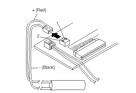
|
Pin |
Voltage (V dc) |
|
1 |
+4 |
|
3 |
Ground |
If the voltage is less than+ 4 V dc, replace the voltage converter.
If the voltage is greater than+ 4 V dc, go to the next step.
6. Power-off the computer.
7. Reconnect the standby battery to the voltage converter.
8. Power-on the computer and leave it approximately 30 minutes to allow the standby battery to be charged.
9. Power-off the computer again and disconnect the standby battery.
10. Measure the voltage of the standby battery.
If the voltage is less than 3.5 V dc, replace the standby battery.
If the voltage is greater than 3.5 V dc, replace the voltage converter.
Testing the Quick Charger:
If an unusual noise can be heard from the operating quick charger, replace it.
1. Perform steps 1 through 3 of the ┐Testing the Battery PackŚ to verify the battery pack is operating correctly.
2. Connect the power cord to the quick charger and the other end to the electrical outlet. Ensure that the power indicator turns on.
If the power indicator does not turn on, check the power cord of the quick charger for proper installation and continuity. If this
does not correct the problem, replace the quick charger.
3. Install the battery pack.
If the charging indicator does not start blinking, replace the quick charger.
Testing the Car Battery Adapter:
If an output voltage from a cigarette lighter socket is less than 10.5 V dc, the power-on indicator on the car battery adapter blinks and a noise can be heard continuously. The battery of the car is defective.
1. Unplug the car battery adapter from the computer if connected.
2. Plug the car battery adapter into the cigarette lighter socket.
Note:
If the adapter is already plugged in, be sure to unplug the adapter from the cigarette lighter socket, then plug it into the socket again.
3. Measure the output voltage of the car battery adapter.

|
Pin |
Voltage (V dc) |
|
1 |
+ 19.0 to+ 21.0 |
|
2 |
Ground |
If the voltage is correct and the power-on indicator on the car battery adapter is on steady, the car battery adapter is working correctly.
If the voltage is out of range, do one of the following.
- Try the above test procedures in another car if available.
- Replace the car battery adapter if the computer works with the AC adapter and does not work with the car battery adapter.
Testing the Voltage Converter:
Use the following procedure to isolate the voltage converter from the problem.
Note:
If the problem occurs only when using the computer with a good battery pack, replace the voltage converter.
1. Power-off the computer.
2. Power-off all attached devices and disconnect them from the computer.
3. Unplug the AC adapter from the computer.
4. Remove the battery pack and the bottom cover.
5. Disconnect the standby-battery connector and the flexible cable from connector CN6 on the voltage converter.
6. Power-off the computer.
7. Plug the AC adapter into the computer.
Important:
The computer goes into suspend mode in about 20 seconds after plugging in the AC adapter. The following procedure must be performed during this period. If the computer is already in suspend mode, unplug the AC adapter and plug it in again to reactivate it.
8. Check the voltages of the voltage converter using the following table.
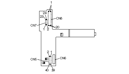
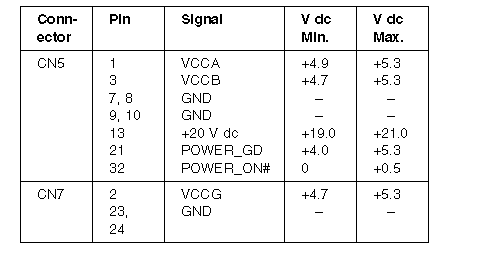
If all the voltages are correct, the voltage converter is good. If+ 20 V dc is not correct, check the output voltage of the AC adapter (see ┐Testing the AC AdapterŚ). If the voltage is correct, replace the voltage converter. If any of the measured voltages except+ 20 V dc is not correct, replace the following FRUs one at a time to correct the problem.
1. Voltage converter
2. System board
3. I/O panel assembly
Note:
Reconnect the standby-battery connector and the flexible cable that were removed in Step 5 before leaving this procedure.
|
Search Keywords |
| |
|
Hint Category |
Hardware Maintenance Information | |
|
Date Created |
10-12-96 | |
|
Last Updated |
01-05-98 | |
|
Revision Date |
28-04-99 | |
|
Brand |
IBM ThinkPad | |
|
Product Family |
Notebook N51 | |
|
Machine Type |
8551 | |
|
Model |
Various | |
|
TypeModel |
| |
|
Retain Tip (if applicable) |
N/A | |
|
Reverse Doclinks |