

|
393.609 bytes |
Service Hints & Tips |
Document ID: LWIK-3SMKN7 |
|
This document is provided to IBM and our Business Partners to help sell and/or service IBM products. It is not to be distributed beyond that audience or used for any other purpose. |
TP 310,315 - Inside Assembly Removal
Applicable to: World-Wide
Inside Assembly:
5 - Hinge Covers
6 - Keyboard Unit
9 - LCD Unit
7 - Thermal plate and CPU
Upper Base:
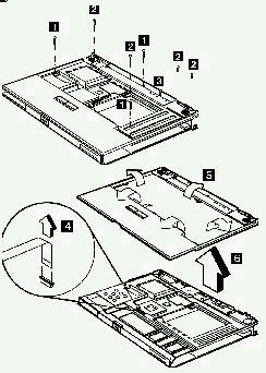
|
Step |
Size (Quantity) |
Head and Color |
Memo |
|
1 |
M2.5 x 18L (3) |
Pan head, silver | |
|
2 |
M2.5 x 6L (4) |
Pan head, black |
w/nylock paste |
|
3 |
M2 x 4L (1) |
Flat head, black |
Note: Be sure to use the correct screw when replacing.
TrackPoint Board, TrackPoint Button and TrackPoint Board FPC Cable:
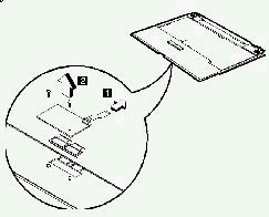
|
Step |
Size (Quantity) |
Head and Color |
Memo |
|
1 |
M2 x 4L (2) |
Pan head, silver |
Note: Be sure to use the correct screw when replacing.
Fan:

Note:
The tape used to secure the fan is not ordinary tape, but a special tape with safety characteristics. This tape is part of the Mylar FRU.
Warning:
The fan cable should follow the path shown in the figure. If the fan cable gets pressed or weighed down and is damaged, the chassis might get short-circuited as a result.
Audio Connector Board:
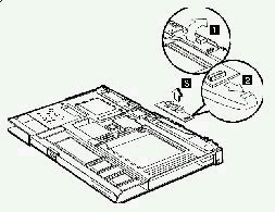
Battery Connector Board:
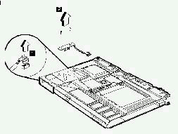
|
Step |
Size (Quantity) |
Head and Color |
Memo |
|
2 |
M2.5 x 6L (2) |
Pan head, black |
w/nylock paste |

Lower Base:
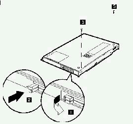
Important:
To remove the chassis with the system board out of the lower base, the PCMCIA slot buttons should be upright then pushed in (1-->2 ) before you begin this removal procedure.
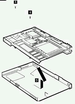
|
Step |
Size (Quantity) |
Head and Color |
Memo |
|
3 |
M2.5 x 6L (2) |
Pan head, black |
w/nylock paste |
|
4 |
M2 x 4L (2) |
Pan head, silver |
Note: Be sure to use the correct screw when replacing.
PCMCIA Door and PCMCIA Door Spring:
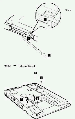
Charger Board:
|
Step |
Size (Quantity) |
Head and Color |
Memo |
|
1 |
M2 x 4L (2) |
Pan head, silver |
Note: Be sure to use the correct screw when replacing.
System Board:
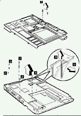
Important:
After replacing the system board, follow the instructions in Setting Thermal Sensor Threshold on page 34 of the HMM.
|
Step |
Size (Quantity) |
Head and Color |
Memo |
|
1 |
M2 x 4L (2) |
Pan head, silver | |
|
2 |
M2 x 4L (2) |
Pan head, black |
w/ nylock paste |
|
3 |
M2 x 4L (2) |
Pan head, silver |
w/ brackets |
|
4 |
M2 x 4L (1) |
Pan head, silver |
Note: Be sure to use the correct screw when replacing.
Backup Battery:
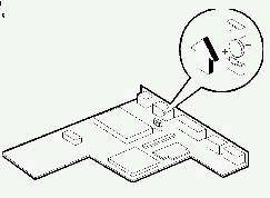
Warning:
The backup battery is a lithium battery and can cause a fire, explosion, or severe burns. Do not charge it, heat it higher than 100›C (212›F), incinerate it, or expose its cell contents to water. Dispose of the battery as required by local ordinances or regulations. Use of an incorrect battery can result in ignition or explosion of the battery. Replacement batteries can be ordered from IBM or IBM authorized dealers.
Keyboard Connector Board:
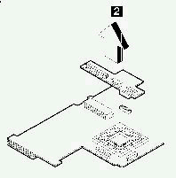
PCMCIA Slot Assembly:
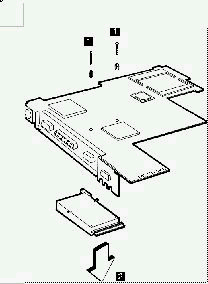
|
Step |
Size (Quantity) |
Head and Color |
Memo |
|
1 |
M2 x 14L (2) |
Pan head, silver |
w/brackets |
|
Search Keywords |
| |
|
Hint Category |
Hardware Maintenance Information | |
|
Date Created |
16-03-98 | |
|
Last Updated |
07-04-98 | |
|
Revision Date |
16-03-99 | |
|
Brand |
IBM ThinkPad | |
|
Product Family |
ThinkPad 310, ThinkPad 315 | |
|
Machine Type |
2600 | |
|
Model |
Various | |
|
TypeModel |
| |
|
Retain Tip (if applicable) |
| |
|
Reverse Doclinks |