
|
51.618 bytes |
Service Hints & Tips |
Document ID: DDSE-3QNJEF |
PCServer704 - Fan Information
Applicable to: World-Wide
Fans

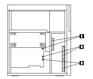
1. Inner chassis fan, connects to Fan 2 header on system board.
2. Outer chassis fan (upper), connects to Fan 3 header on system board
3. Outer chassis fan (lower), connects to Fan 4 header on system board
Inner Chassis Fan
Note
The fan bracket assembly is not held together with screws. As you remove the assembly from the chassis, do not let the parts fall.
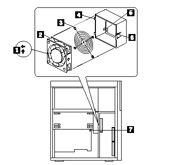
1. Press the release tabs on the side of fan bracket. Rotate the assembly outward from until the tabs on the opposite side of the bracket clear the slots in the chassis.
2. Lift the fan out of the bracket, pulling up the cable around the grill.

1. Airflow direction arrows on side of fan, center label on fan facing back of chassis
2. Inner chassis fan
3. Protective grill
4. Hinge tabs on inner edge of bracket
5. Slot in bracket for routing power cable (and through grommeted hole, not shown, beyond inner edge of bracket
6. Bracket release tab
7. Fan 2 header on system board
Outer Chassis Fan

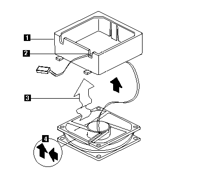
1. Bracket oriented as shown
2 . Power cable routed through slot
3. Wavy arrow indicates airflow direction
4. Airflow direction arrows embossed on side of fan
|
Search Keywords |
| |
|
Hint Category |
Hardware Maintenance Information | |
|
Date Created |
14-06-96 | |
|
Last Updated |
28-05-98 | |
|
Revision Date |
27-05-99 | |
|
Brand |
IBM PC Server | |
|
Product Family |
PC Server 704 | |
|
Machine Type |
8650 | |
|
Model |
| |
|
TypeModel |
| |
|
Retain Tip (if applicable) |
| |
|
Reverse Doclinks |