
|
50.697 bytes |
Product Information |
Document ID: MCGN-45VW39 |
Netfinity 5500 M20 - Input/output connectors and expansion slots
Applicable to: World-Wide
Source: Hardware Maintenance Manual
Input/output connectors and expansion slots
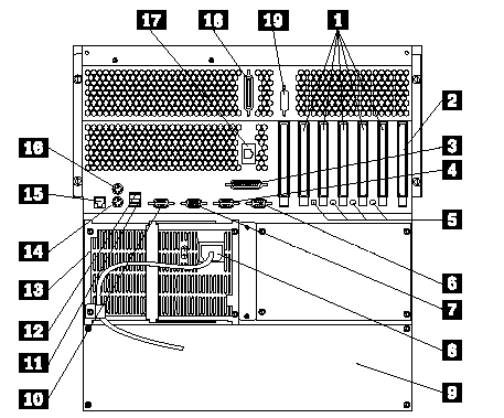
The following illustration shows the expansion slots and the input/output connectors (ports) on the rear of the server.

1 PCI Expansion Slots: The server has five peripheral component interconnect (PCI) expansion slots. Four of the PCI slots support hot-plug PCI adapters. The remaining, non-hot-plug PCI slot supports only a short adapter. Many adapters provide bus-master capabilities, which enable the adapters to perform operations
without interrupting the system microprocessors.
2 ISA Expansion Slot: The server has one industry standard architecture (ISA) expansion slot. Many adapters provide bus-master capabilities, which enable the adapters to perform operations without interrupting the system microprocessors.
3 Parallel Connector: A signal cable for a parallel device, such as a printer, connects here.
4 Serial A Connector: A serial signal cable for a modem or other serial device connects to this 9-pin serial connector. Serial port A can be shared by the Netfinity Advanced System Management Processor and the operating system. See "Devices and I/O ports" for port assignment information. If you are using a 25-pin signal cable, you need a 9-pin-to-25-pin adapter cable.
5 Attention Lights for Hot-Plug PCI Slots: Each hot-plug PCI slot has an Attention light that is visible from the rear of the server. An Attention light flashes approximately once per second when it is on. The meaning of the Attention lights is defined by the operating system. Refer to the operating system documentation to determine if it supports hot-plug PCI adapters and, if so, what the Attention lights indicate.
6 Serial B Connector: A serial signal cable for a modem or other serial device connects to this 9-pin serial connector. Serial port B is used by the operating system and cannot be shared by the Netfinity Advanced System Management Processor. See "Devices and I/O ports" for port assignment information. If you are using a 25-pin signal cable, you need a 9-pin-to-25-pin adapter cable.
7 Video Connector: The monitor signal cable connects here.
8 Power Supply 1 Power Connector: The power cord for power supply 1 connects here.
9 NetBAY3: The tower models of the Netfinity 5500 M20 come with a NetBAY3 attached. You can install devices, such as the IBM EXP10 or a power distribution unit, in the NetBAY3. Refer to "Installing devices in the NetBAY3" for more information.
10 Management C Connector: This connector is used to attach a modem that is dedicated to communication with the Netfinity Advanced System Management Processor.
11 Universal Serial Bus 2 Connector: You can attach an I/O device to this universal serial bus (USB) connector. You need a 4-pin cable to connect devices to USB 1 or 2.
|
Note |
|
Note |
14 Keyboard Connector: The keyboard cable connects here.
15 Ethernet Connector: The server has one RJ-45 Ethernet connector. This connector is for attaching the network cable to the integrated 10BASE-T or
100BASE-TX, twisted-pair transceiver.
16 Mouse Connector: The mouse cable connects here. This port sometimes is called an auxiliary-device or pointing-device port.
17 Management RS-485 Connector: This connector is for connecting rack or multirack systems through a daisy-chain cable in half-duplex mode.
18 SCSI Connector: External SCSI devices attach here.
19 External Connector Knockout: The server has one external connector knockout that can be used when you install options.
|
Note |
|
Search Keywords |
| |
|
Document Category |
Diagrams | |
|
Date Created |
12-03-99 | |
|
Last Updated |
21-05-99 | |
|
Revision Date |
16-03-2000 | |
|
Brand |
IBM PC Server | |
|
Product Family |
Netfinity 5500 M20 | |
|
Machine Type |
8662 | |
|
Model |
ALL | |
|
TypeModel |
| |
|
Retain Tip (if applicable) |
| |
|
Reverse Doclinks |