
|
76.184 bytes |
Service Hints & Tips |
Document ID: GSMH-3DKCZF |
TP Selectadock II - Checkout Guide
Applicable to: World-Wide
Checkout Guide:
Use the following procedure as a guide for computer problems.
Note:
The diagnostic tests are intended to test only IBM products. Non-IBM products, prototype cards, or modified options can give false errors and invalid system responses.
Important:
When the problem determination procedure in the operation manual that is supplied with the adapter or device says 'Have the system unit serviced—, this means both the computer and the SelectaDock Docking System.
1. Obtain the failing symptoms in as much detail as possible.
2. Verify the symptoms by attempting to re-create the failure by running the diagnostic test or by repeating the same operation.
Note:
To run the diagnostics, refer to 'How to Run the Diagnostics—.
3. Use the following table with the verified symptom to determine which page to go to. Search the symptoms column and find the description that best matches your symptom; then go to the page shown in the 'Go to— column.
|
Symptoms (Verified) |
Go to |
|
Power failure. (The power indicator does not go on or stay on.) |
'Power Supply—. |
|
POST does not complete. No beeps or error code are indicated. |
'Symptom-to-FRU Index—, and then use the No Beep Symptoms table. |
|
The configuration is not the same as the installed devices. |
'Checking the Installed Devices List—. |
|
POST beeps, but no error codes are displayed. |
Symptom-to-FRU Index—, and then use the Beep Symptoms table. |
|
POST detected an error and displayed numeric error codes. |
Symptom-to-FRU Index—, and then use the Numeric Error Codes table. |
|
The diagnostic test detected an error and displayed a FRU code. |
'Diagnostic Error Codes—. |
|
Other symptoms (such as LCD display problems). |
'Symptom-to-FRU Index—, and then use the other symptom table. |
|
Symptoms cannot be re-created (intermittent Use the customer reported symptoms and go to problems). |
'Symptom-to-FRU Index—. |
Power Supply:
If the power-on indicator is not on but the power supply fan is not turning, check the power cord for continuity and correct installation.
If the power cord is not the problem, either the power supply is defective, or another component is defective causing the power supply to cut off.
To verify the power supply is operating correctly, do the following:
1. Power-off the computer and disconnect the SelectaDock Docking System power cord.
2. Remove all internal devices, external devices, and the computer from the SelectaDock Docking System.
3. Undock the Base Model.
4. Remove the half-height bay frame (see '1050 Half-Height Bay Frame—).
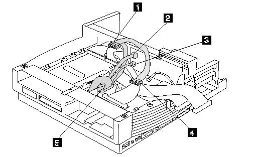
5. Remove connectors 1, 2,3,4, and 5 from the each device, tray, or card.

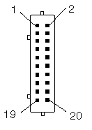
6. Short-circuit1 and 3,2 and 8 of the connector 5. Then check the power supply voltages on each connector. If the voltage is not correct, replace the power supply.
If any of the voltages is not correct, replace the power supply. If replacing the power supply does not correct the problem, replace the main card.
Power Supply Connector 1 and 4

|
Pin |
V dc |
|
Red cord |
+ 5 V |
|
Yellow cord |
+ 12 V |
Power Supply Connector 2:

|
Pin |
Signal |
V dc Min. |
V dc Max. |
|
1,2 |
CVCC |
+ 19 V |
+ 21 V |
|
3,4 |
GND |
- |
- |
Power Supply Connector 3:

|
Pin |
Signal |
V dc Min. |
V dc Max. |
|
1 |
- 12 V |
- 11.4 V |
- 13.2 V |
|
2,3 |
GND |
- |
- |
|
4 |
- 5 V |
- 4.53 V |
- 5.5 V |
Power Supply Connector 5:

|
Pin |
Signal |
V dc Min. |
V dc Max. |
|
2,3 |
GND |
- |
- |
|
4 |
SUB 12 |
+ 11.4 |
+ 12.6 |
|
5 |
GND |
- |
- |
|
6,7 |
+ 12 volts |
+ 11.4 |
+ 12.6 |
|
8 |
GND |
- |
- |
|
9-11 |
+ 3.3 |
+ 3.0 |
+ 3.6 |
|
12-14 |
GND |
- |
- |
|
15-17 |
+5 |
+ 4.75 |
+ 5.25 |
|
18-20 |
GND |
- |
- |
If a device that is not installed appears in a dark shade (for example, FDD-2 appears in a dark shade when NO second FDD is installed), do the following:
1. Replace the first device in the configuration, such as an FDD-1, HDD-1.
2. If the problem remains, replace the system board.
The PCMCIA-1, parallel, and serial icons are always displayed in a dark shade because the icons represent subsystems of the system board and not the attachment of the devices.
The FDD-1, HDD-1, or PCMCIA-1 icons represent the first drive in the system configuration for each type of device. Similarly, the HDD-3, FDD-2, or PCMCIA-2 icons represent the second drive, usually attached through a port replicator or an expansion unit.
The HDD-2 icon represents the hard disk drive in the UltraBay of the computer. The HDD-3 or HDD-4 icons represent the hard disk drive in the SelectaDock Docking System (except the SCSI hard disk). The FDD-2 or PCMCIA-2 icons represent the FDD or PCMCIA attached through a port replicator or in the SelectaDock Docking System.
Printer:
Test the printer by connecting it to the computer before testing it on the SelectaDock Docking System.
1. Make sure the printer is correctly connected and is powered on.
2. Run the printer self-test.
If the printer self-test does not run correctly, the problem is in the printer. Refer to the printer service manual.
If the printer self-test runs correctly, connect a wrap plug on the parallel connector on the rear of SelectaDock Docking System and run the advanced diagnostic tests to determine the failing FRU.
If the advanced diagnostic tests (with the wrap plug connected) did not detect a failure, replace the printer cable.
If the problem is not corrected, do one of the following:
- If the printer is attached to the parallel connector of SelectaDock Docking System, replace the main card of SelectaDock Docking System.
If the printer is attached to the parallel connector on the adapter, replace the FRUs in the following order one at a time until the problem is corrected:
Note:
If the replaced FRUs do not resolve the problem, put the original FRUs back in the SelectaDock Docking System. Do not replace nondefective FRUs.
1. Adapter
2. Main card of SelectaDock Docking System
External Display:
If the screen is rolling, replace the external display.
If the problem is not corrected, replace FRUs in the following order one at a time until the problem is corrected:
Note:
If the replaced FRUs do not resolve the problem, put the original FRUs back in the SelectaDock Docking System. Do not replace nondefective FRUs.
If the external display is attached to the SelectaDock Docking System:
1. Main card of SelectaDock Docking System
If the external display is attached to the display adapter:
1. Display adapter
2. Main card of SelectaDock Docking System
3. Riser card
If the screen is not rolling, do the following to run the display self-test:
1. Power-off the computer on the SelectaDock Docking System and the external display.
2. Disconnect the external display signal cable from the SelectaDock Docking System.
3. Power-on the external display.
4. Turn the contrast control to its maximum position.
5. Turn the brightness control to its center detect position.
Check for the following conditions:
The screen should be white or light gray, with a black margin. See the appropriate display manuals for the correct self-test condition. The screen contrast and brightness controls should change the intensity of the screen.
If the external display does not meet these specifications, replace the external display.
If the external display meets these specifications, replace FRUs in the following order one at a time until the problem is corrected.
Note:
If the replaced FRUs do not resolve the problem, put the original FRUs back in the SelectaDock Docking System. Do not replace nondefective FRUs.
If the external display is attached to the SelectaDock Docking System:
1. Main card of SelectaDock Docking System
2. External display
If the external display is attached to the display adapter:
1. Display adapter
2. Main card of SelectaDock Docking System
3. Riser card
4. External display
External Keyboard:
Notes:
If a mouse or other pointing device is attached, remove it and see if the error symptom goes away. If the symptom goes away, the mouse or other pointing device is defective.
The computer keyboard does not work when an external keyboard is connected.
1. Power-off the computer.
2. Disconnect the keyboard cable from the external keyboard.
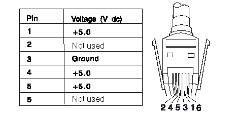
3. Power-on the computer and check the keyboard cable connector for the following voltages. All voltages have (+/-) 5% voltage tolerance.

4. If all voltages are correct, replace the external keyboard.
5. If the voltages are not correct, replace the following FRUs one at a time until the problem is corrected.
Note:
If the replaced FRUs do not resolve the problem, put the original FRUs back in the SelectaDock Docking System. Do not replace nondefective FRUs.
a. Keyboard cable
b. Main card of the SelectaDock Docking System
|
Search Keywords |
| |
|
Hint Category |
Hardware Maintenance Information | |
|
Date Created |
22-01-97 | |
|
Last Updated |
27-08-98 | |
|
Revision Date |
21-08-99 | |
|
Brand |
IBM ThinkPad | |
|
Product Family |
ThinkPad Docking Stations | |
|
Machine Type |
3547 | |
|
Model |
| |
|
TypeModel |
| |
|
Retain Tip (if applicable) |
N/A | |
|
Reverse Doclinks |