
|
41.748 bytes |
Parts Information |
Document ID: DDSE-44JG8W |
Netfinity 3500 - Memory Modules
Applicable to: World-Wide
Memory Modules
|
Notes |

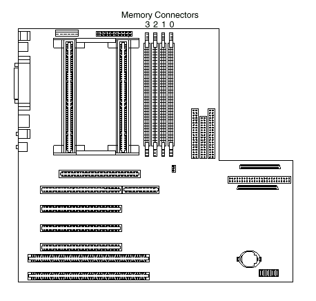
Memory Configuration: When adding or removing memory, a basic rule to follow is to fill each system memory connector sequentially, starting at Bank 0.
Table 6 on page 82 shows the suggested memory configurations for the server. The contents of this table and additional information can be found on a label located inside the server. Again, alternate configurations are possible.
|
Note |
|
Total Memory |
Bank 0 |
Bank 1 |
Bank 2 |
Bank 3 |
|
32 |
32 |
0 |
0 |
0 |
|
64 |
64 |
0 |
0 |
0 |
|
64 |
32 |
32 |
0 |
0 |
|
96 |
32 |
32 |
32 |
0 |
|
128 |
128 |
0 |
0 |
0 |
|
128 |
64 |
64 |
0 |
0 |
|
256 |
128 |
128 |
0 |
0 |
|
256 |
128 |
64 |
64 |
0 |
|
512 |
128 |
128 |
128 |
128 |
|
Search Keywords |
| |
|
Document Category |
Memory | |
|
Date Created |
27-01-99 | |
|
Last Updated |
27-01-99 | |
|
Revision Date |
27-01-2000 | |
|
Brand |
IBM PC Server | |
|
Product Family |
Netfinity 3500 | |
|
Machine Type |
8644 | |
|
Model |
| |
|
TypeModel |
| |
|
Retain Tip (if applicable) |
| |
|
Reverse Doclinks |