

|
238.583 bytes |
Parts Information |
Document ID: DDSE-44JLZA |
Netfinity 7000 - System Board
Applicable to: World-Wide
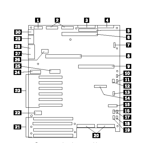
|
1 |
Power control and status cable |
|
2 |
+5V, +12V, and 3.3V power connectors (identical) |
|
3 |
Diskette-drive connector |
|
4 |
Front-panel connector |
|
5 |
IDE connector |
|
6 |
Memory-board connector |
|
7 |
Not used |
|
8 |
Secondary processor-board connector |
|
9 |
Primary processor-board connector |
|
10 |
Fan 1 connector (not used, jumper required) |
|
11 |
Fan 2 connector (not used, jumper required) |
|
12 |
Hard disk drive LED 1 connector |
|
13 |
Not used |
|
14 |
Not used |
|
15 |
Server management connector |
|
16 |
IC2 |
|
17 |
Fan 3 connector (not used, jumper required) |
|
18 |
Fan 4 connector (jumper required unless optional thermal upgrade kit is used) |
|
19 |
Hard disk drive LED 2 connector |
|
20 |
SCSI channels A (right) and B (left) connectors |
|
21 |
EISA/ISA slots 1 4 for adapters (slot 1 toward top of illustration, slot 4 toward bottom) |
|
22 |
Not used |
|
23 |
PCI slots 1 6 for adapters (slot 1 toward top of |
|
24 |
Configuration switches and jumpers |
|
25 |
Real-time clock |
|
26 |
Video memory DRAM connector |
|
27 |
VGA monitor connector |
|
28 |
Parallel-port connector |
|
29 |
Serial-port connectors A (COM1) and B (COM2) |
|
30 |
PS/2-compatible keyboard and mouse |
|
Note |
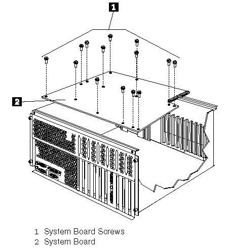
To remove the system board, do the following:
1. Remove the top cover, see "Cover (Top)".
2. Remove the processor and memory boards, see "Processor or Memory Board".
3. Remove the adapters, see "Adapters".
4. Remove the CEC, see "Central Electronics Complex (CEC)".
5. Remove the 14 system board screws 1 and remove the system board 2 .
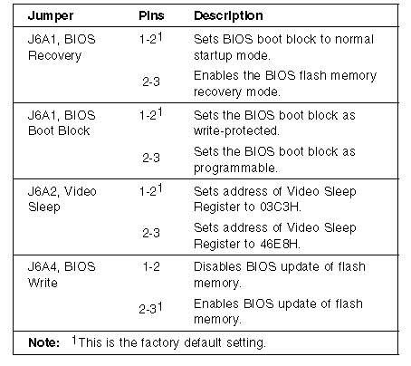
Enabling BIOS Recovery Mode (J6A1): The flash memory contains a protected area that cannot be corrupted. The code in this area enables the server to start from a diskette when the BIOS becomes corrupted, for example, if a power failure occurs during a flash update. After starting, the Flash Memory Update Utility automatically recovers the system BIOS from the BIOS recovery files on the diskette.
|
Notes: |
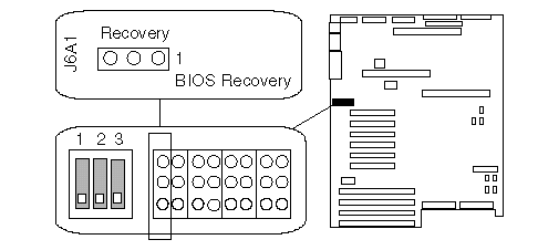
3. If the primary processor board blocks access to the jumper, remove it (see "Processor or Memory Board ").
4. Move the jumper to pins 2 and 3. This enables the recovery mode.
5. If you removed the primary processor board, install it.
6. Replace the top cover.
7. Insert the flash memory update diskette into the primary diskette drive (usually drive A).
8. Connect the power cable to the server.
9. Start the server.
After the server successfully completes POST, the speaker emits a single beep and the recovery process starts (the process takes about three minutes). During the recovery process, no messages are displayed on the monitor, and the keyboard is disabled. When the recovery process is complete, the server emits two beeps.
10. Power-off the server and all peripheral devices, remove the top cover (see "Cover (Top)"), and move the jumper back to its original position (pins 1 and 2, factory default).
BIOS Boot Block Jumper Setting (J6A1)
|
Note |
To be able to program the boot block:
1. Power-off the server and peripheral devices and remove the top cover (see "Cover (Top)").
2. Identify the BIOS boot block jumper, J6A1.
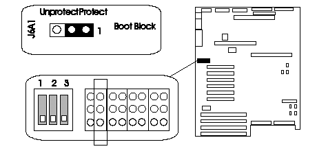
3. If the primary processor board blocks access to the jumper, remove it (see Processor or Memory Board").
4. Set the BIOS boot block jumper:
a. To remove the write-protection from the BIOS boot block, move the jumper to pins 2 and 3.
b. To set the write-protection on the BIOS boot block, move the jumper to pins 1 and 2 (factory default).
5. If you removed the primary processor board, install it.
Video-Sleep-Register Address Setting (J6A2):
The Video-Sleep-Register jumper determines which I/O port the SVGA controller uses for its internal AT mode setup port. The starting address of the default port is 03C3H (pins 1 and 2). When this jumper is set to pins 2 and 3, the Video-Sleep-Register address changes to 46E8H.
If no keyboard activity occurs after a specified timeout period (1 to 128 minutes, as specified through the Setup program), the Video-Sleep-Register jumper blanks out the monitor screen. When this happens, you must enter a password to reactivate the monitor and keyboard.
To change the location of the Video Sleep Register:
1. Power-off the server and peripheral devices and remove the top cover (see "Cover (Top)").
2. Identify the Video-Sleep-Register jumper, J6A2.
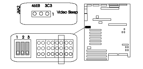
3. If the primary processor board blocks access to the jumper, remove it (see Processor or Memory Board").
4. Set the address of the Video-Sleep Register:
a. To set the address to 03C3H (factory default), move the jumper to pins 1 and 2.
b. To set the address to 46E8H, move the jumper to pins 2 and 3.
5. If you removed the primary processor board, install it.
BIOS Write Jumper Setting (J6A4)
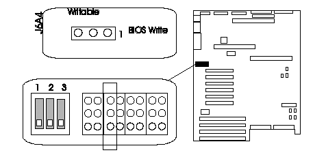
This jumper enables updating the BIOS in flash memory with a special utility. The factory default leaves this function enabled so that you can update the BIOS from a startable diskette without having to open the server covers and change the jumper.
System-Board Configuration Switch Settings: Some configuration actions are controlled through switches on the system board. Table 9 summarizes the switch settings that correspond to these actions.
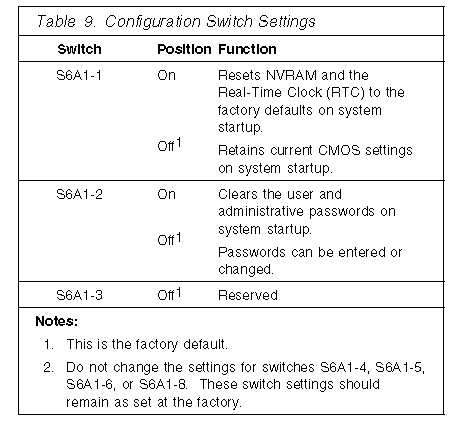
NVRAM and RTC Settings (Switch S6A1-1): Setting the CMOS switch to On clears the current values of NVRAM and the RTC when the server is reset. This returns NVRAM and the RTC to the factory default.
When the CMOS switch is set to Off, the default, the current settings are preserved during system reset.
To reset the server's NVRAM and RTC settings to the factory default values:
1. Power-off the server and peripheral devices and remove the top cover (see "Cover (Top)").
2. If the primary processor board blocks access to the switch, remove it (see "Processor or Memory Board").
3. Locate the configuration switches on the system board.
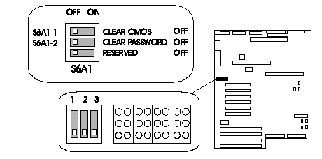
4. Slide switch S6A1-1 to On.
5. If you removed the primary processor board, replace it.
6. If ISA cards are installed, remove them.
7. Replace the top cover.
8. Connect the power cords to the server and the monitor.
9. Power-on the server and the monitor; then, wait for POST to complete. This automatically reprograms the NVRAM and RTC to their factory settings.
10. Power-off the server and the monitor.
11. Disconnect the power cords from the server and monitor.
12. Remove the top cover.
13. If the primary processor board blocks access to the switch, remove it (see "Processor or Memory Board").
14. Slide switch S6A1-1 to Off.
15. If you removed the primary processor board, replace it.
16. If you removed the ISA cards, do the following.
a. Boot the IBM Netfinity 7000 System CD-ROM and select System Configuration.
b. Add the ISA cards to the configuration.
c. Save the configuration.
d. Install the ISA cards you removed in 6.
Clearing All Passwords (Switch S6A1-2): Setting the password switch to On clears the administrative and user passwords.
When the password switch is set to Off, which is the default, you can enter an administrative or user password, or both.
To clear the administrative and user passwords or allow a password to be set:
1. Power-off the server and peripheral devices and remove the top cover (see "Cover (Top)").
2. If the primary processor board blocks access to the switch, remove it (see "Processor or Memory Board").
3. Locate the configuration switches on the system board.
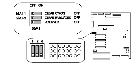
4. Slide switch S6A1-2 to On.
5. If you removed the primary processor board, replace it.
6. Connect the power cords to the server and the monitor.
7. Power-on the server and the monitor; then, wait for POST to complete. This automatically clears the administrative password.
8. Power-off the server and the monitor.
9. Disconnect the power cords from the server and monitor.
10. If the primary processor board blocks access to the switch, remove it (see "Processor or Memory Board").
11. Slide switch S6A1-2 to Off.
12. If you removed the primary processor board, replace it.
13. Run the System Configuration Utility program to specify a new administrative password, user password, or both (see "Security").
|
Search Keywords |
| |
|
Document Category |
System Boards | |
|
Date Created |
27-01-99 | |
|
Last Updated |
27-01-99 | |
|
Revision Date |
27-01-2000 | |
|
Brand |
IBM PC Server | |
|
Product Family |
Netfinity 7000 | |
|
Machine Type |
8651 | |
|
Model |
| |
|
TypeModel |
| |
|
Retain Tip (if applicable) |
| |
|
Reverse Doclinks |