
|
107.566 bytes |
Product Information |
Document ID: DDSE-433LKK |
Netfinity 5000 - Input / Output Connectors
Applicable to: World-Wide
Input / Output Connectors
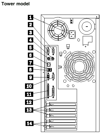
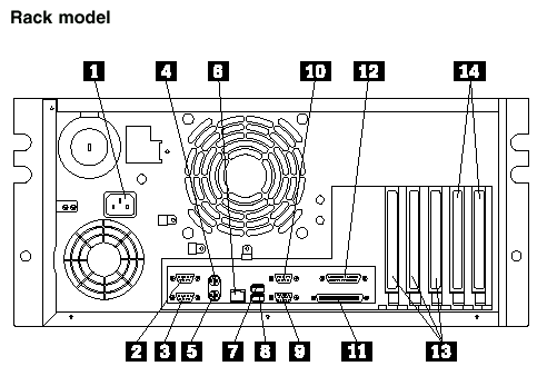
The following illustrations identify the connectors located on the back of the server.


 The server power cable connects here.
 Signal cables for modems or other serial devices connect here to the 9-pin serial connector for serial port A. See Devices and I/O Ports for port assignment information.
 Signal cables for modems or other serial devices connect here to the 9-pin serial connector for serial port B. See Devices and I/O Ports for port assignment information.
 The mouse cable connects here. This connector is sometimes called the auxiliary-device port.
 The keyboard cable connects here.
 An unshielded, twisted-pair cable with an RJ-45 connector attaches here to the 10/100 Ethernet controller on the system board.
 Attach I/O devices with universal serial bus (USB) connectors to USB connector 1. You need a 4-pin cable to connect a device to this port.
 Attach I/O devices with universal serial bus (USB) connectors to USB connector 2. You need a 4-pin cable to connect a device to this port.
 The monitor signal cable connects here.
 The cable to attach a modem that is dedicated to communication with the system-management processor connects here.
 External SCSI devices attach here. For more information, see External Options.
 A signal cable for a parallel device, such as a printer, connects here.
 Cables to the external connectors on PCI adapters connect here (slots 3, 4, and 5).
 Cables to the external connectors on either ISA or PCI adapters connect here (slots 1 and 2).
|
Search Keywords |
| |
|
Document Category |
Diagrams | |
|
Date Created |
11-12-98 | |
|
Last Updated |
11-12-98 | |
|
Revision Date |
11-12-99 | |
|
Brand |
IBM PC Server | |
|
Product Family |
Netfinity 5000 | |
|
Machine Type |
8659 | |
|
Model |
ALL | |
|
TypeModel |
| |
|
Retain Tip (if applicable) |
| |
|
Reverse Doclinks |