
|
54.943 bytes |
Parts Information |
Document ID: DDSE-42DUZJ |
Netfinity 3000 - Memory Modules
Applicable to: World-Wide
Memory Modules
Adding system memory to the server can make programs run faster. You can increase the amount of system memory by installing options called memory modules.
The maximum amount of system memory the server supports is 384 MB. You can add memory to the server to increase system performance. The server has three connectors for installing system-memory modules.
|
Note |

The memory modules that the server uses are dual-inline memory modules (DIMMs). The DIMMs that come with the server are synchronous dynamic random-access memory (SDRAM) with error checking and correction (ECC). These memory modules have a speed of 100 MHz. You can add extra memory modules or replace existing memory modules.
When installing or replacing DIMMs, follow these guidelines:
- The server comes with one or more dual-inline memory modules (DIMMs) installed.
- Install DIMMs with a maximum height of 6.35 cm (2.5 inches).
- Use only 3.3 V dc unbuffered, 100 MHz SDRAM DIMMs.
- Each memory connector supports a maximum of 128 MB of memory. However, the maximum amount of system memory the server supports is 384 MB.
- Install only ECC DIMMs to enable ECC. If you install nonparity (NP) DIMMs, the server will not power up, and POST memory error code 164 will be displayed.
- If you are installing DIMMs of different sizes, install the DIMMs with greater memory capacity starting with the connector closest to the edge of the system board (DIMM 2).
- After installing or removing a DIMM, you must save the new configuration information using the Configuration/Setup Utility program. See "Configuration/Setup Utility Program Menus".
- For more information about the DIMMs that the server supports, go to the following World Wide Web address:
http://www.pc.ibm.com/us/compat/
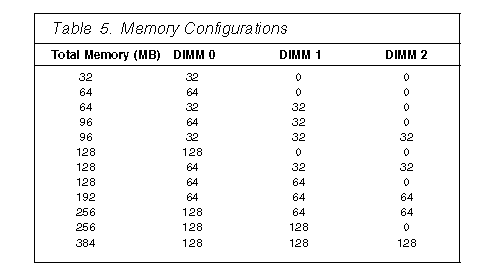
Memory Configuration: When you are adding or removing memory, fill each system memory connector sequentially, starting at DIMM 0.
Table 5 shows the some of the possible memory configurations for the server. The contents of this table and additional information can be found on a label located inside the server. Alternative configurations are possible.

|
Note |
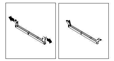
This section gives the procedure for installing memory modules. If you want to remove a memory module, reverse the order of the following steps.
|
Before you begin: |
|
Notes |

4. Touch the static-protective package containing the DIMM to any unpainted metal surface in the server; then, remove the DIMM.
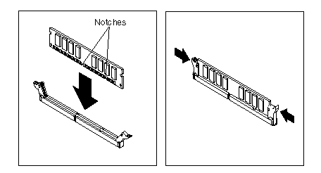
5. Position the DIMM above the connector so that the two notches on the bottom edge of the DIMM align properly with the connector.
6. Firmly push the DIMM straight down into the connector until the retaining clips close and snugly fit around both ends of the DIMM.

|
Note |
|
Search Keywords |
| |
|
Document Category |
Memory | |
|
Date Created |
20-11-98 | |
|
Last Updated |
23-11-98 | |
|
Revision Date |
20-11-99 | |
|
Brand |
IBM PC Server | |
|
Product Family |
Netfinity 3000 | |
|
Machine Type |
8476 | |
|
Model |
ALL | |
|
TypeModel |
| |
|
Retain Tip (if applicable) |
| |
|
Reverse Doclinks |