
|
85.037 bytes |
Service Hints & Tips |
Document ID: GSMH-3CAD5B |
|
This document is provided to IBM and our Business Partners to help sell and/or service IBM products. It is not to be distributed beyond that audience or used for any other purpose. |
TP General - N45SL FRU Removals and Replacements
Applicable to: World-Wide
FRU Removals and Replacements:
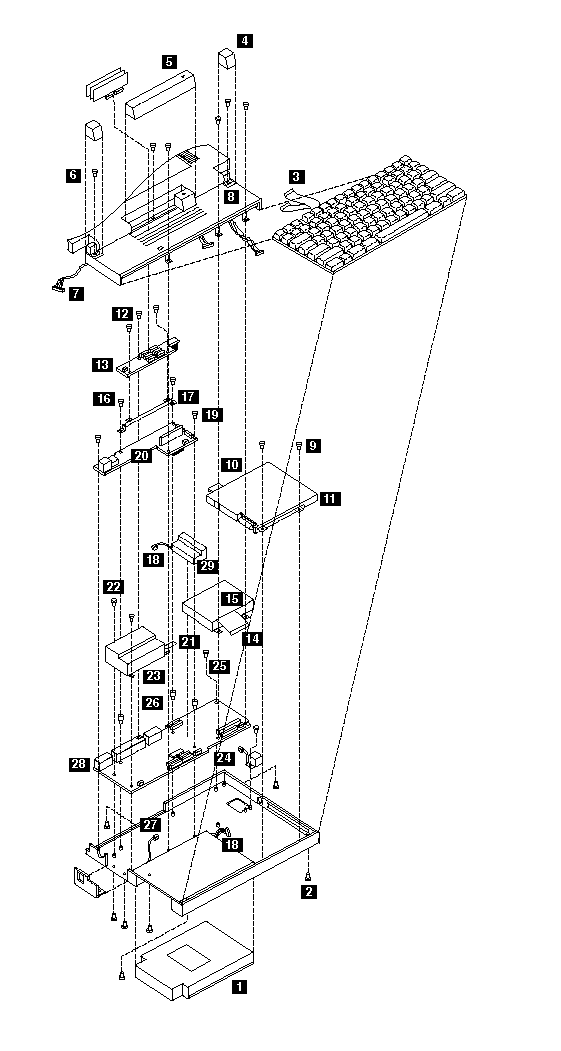
Follow the numerical sequence in the FRU removal sequence list and the exploded view to remove or disconnect parts in the correct order. The letters in parentheses in the list indicate screw types. See the -- 'Screw Chart Size' -- to match the letters to the correct screw type and size before replacing each screw.
Safety Notice 8:
Before removing any FRU, power-off the computer, unplug all power cords from electrical outlets, remove the battery pack, then disconnect any interconnecting cables.
Safety Notice 1:
Before the computer is powered-on after FRU replacement, make sure all screws, springs, or other small parts are in place and are not left loose inside the computer. Verify this by shaking the computer and listening for rattling sounds. Metallic parts or metal flakes can cause electrical shorts.
|
1 |
Battery Pack |
|
2 |
Three Screws (1-G, 2-J) |
|
3 |
Two Ribbon Cables and Remove Keyboard |
|
4 |
Hinge Covers |
|
5 |
Memory Module Cover |
|
6 |
Three Screws (1-J, 2-WW) |
|
7 |
Three LCD Assembly Cables |
|
8 |
Three Screws and LCD Assembly |
|
9 |
Two Screws (J) |
|
10 |
Diskette Drive Ribbon Cable |
|
11 |
Diskette Drive |
|
12 |
Three Screws (J) (Move shielding aside. Do not crease shielding.) |
|
13 |
Memory Module Expansion Card |
|
14 |
Hard Disk Drive Ribbon Cable |
|
15 |
Hard Disk Drive |
|
16 |
Two Screws (J) |
|
17 |
Memory Module Support Bracket |
|
18 |
Backup Battery, Battery Compartment Cables |
|
19 |
Two Screws (J) |
|
20 |
DC to DC PCB Assembly |
|
21 |
Modem Ribbon Cable |
|
22 |
Three Modem Housing Screws (J) |
|
23 |
Modem Housing Assembly |
|
24 |
Mouse Cable |
|
25 |
One System Board Screw (J) |
|
26 |
Three System Board Threaded Hex Spacers |
|
27 |
Cable |
|
28 |
System Board |
|
29 |
Backup Battery |
Model N45 Exploded View:

|
Search Keywords |
| |
|
Hint Category |
Hardware Maintenance Information | |
|
Date Created |
12-12-96 | |
|
Last Updated |
01-05-98 | |
|
Revision Date |
28-04-99 | |
|
Brand |
IBM ThinkPad | |
|
Product Family |
Notebook N45 | |
|
Machine Type |
2614 | |
|
Model |
Various | |
|
TypeModel |
| |
|
Retain Tip (if applicable) |
N/A | |
|
Reverse Doclinks |