
|
68.638 bytes |
Service Hints & Tips |
Document ID: GSMH-3D4FDM |
|
This document is provided to IBM and our Business Partners to help sell and/or service IBM products. It is not to be distributed beyond that audience or used for any other purpose. |
TP 510 - FRU Removals and Replacements
Applicable to: World-Wide
FRU Removals and Replacements:
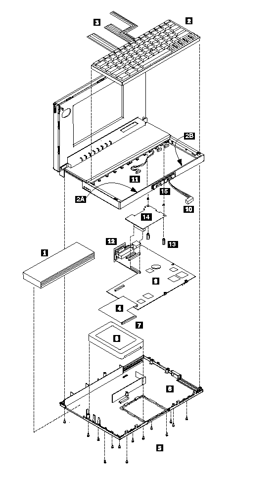
Follow the list below for the sequential removal of FRUs. See the illustration on ¿ThinkPad 510 Exploded View— for
locations and identification of FRUs. The letters in parentheses in the list indicate screw types. See ¿Bottom Cover Screws— to match the letters to the correct screw type and size before replacing each screw.
Safety Notice 8:
Before removing any FRU, power-off the computer, unplug all power cords from electrical outlets, remove the battery pack, then disconnect any interconnecting cables.
Safety Notice 1:
Before the computer is powered-on after FRU replacement, make sure all screws, springs, or other small parts are in place and are not left loose inside the computer. Verify this by shaking the computer and listening for rattling sounds. Metallic parts or metal flakes can cause electrical shorts.
1. Remove Battery Pack
2. Lift Keyboard
(Tabs located along the inside front edge of the keyboard hold the keyboard in the bottom cover. Insert a small screwdriver at 2A and 2B, between the front of the keyboard and the bottom cover. Gently pry the bottom cover away from the keyboard to release the keyboard.)
3. Disconnect Three Ribbon Cables
Remove Keyboard
CAUTION:
Be careful not to scratch the LEDs or LCD display when removing the keyboard
(If you are removing the system board, disconnect all flat cables. Slide each connector latch retainer away from the base to release each cable.)
4. Disconnect Hard Disk Drive Ribbon Cable
(Disconnect the cable at the system board connector.)
5. Remove Bottom Cover Screws
See ¿Bottom Cover Screws—.
(2-G screws near mouse buttons) (1-EE screw in center)
(2-DD screws between the right mouse button and the PCMCIA slot)
(5-EE screws around bottom cover perimeter)
6. Remove Bottom Cover (with Hard Disk Drive and Cable Attached)
CAUTION:
When removing the bottom cover, be careful not to damage the PCMCIA test card.
(Slide the bottom cover past the PCMCIA eject button as you lift the cover off.)
(If you are not removing the hard disk drive, go to step 9.)
7. Disconnect Hard Disk Drive Ribbon Cable
(Disconnect the cable from the hard disk drive.)
8. Remove the Hard Disk Drive
(4-G screws near FCC notice)
9. Lift System Board
(Gently lift the system board and turn it over. Be careful not to lose the two plastic system board inserts.)
10. Disconnect Pointing Device Cable
11. Disconnect LCD Display Cable
12. Disconnect Parallel Port Cable
(In metal frame on system board rear)
Power Switch Assembly, see ¿Parts Listing—.
13. Remove Two Threaded Power Card Spacers
14. Remove Power Card
15. Remove Mouse Buttons
ThinkPad 510 Exploded View:

|
Search Keywords |
| |
|
Hint Category |
Hardware Maintenance Information | |
|
Date Created |
07-01-97 | |
|
Last Updated |
15-04-98 | |
|
Revision Date |
09-04-99 | |
|
Brand |
IBM ThinkPad | |
|
Product Family |
ThinkPad 510 | |
|
Machine Type |
2604 | |
|
Model |
Various | |
|
TypeModel |
| |
|
Retain Tip (if applicable) |
N/A | |
|
Reverse Doclinks |