
|
61.839 bytes |
Service Hints & Tips |
Document ID: MCGN-3R4NRK |
PC Server 325 - PC Server Advanced Systems Management Adapter (FRU No. 76H3240)
Applicable to: World-Wide
|
Note |
|
Note |
System and Adapter Configuration
The IBM PC Server Advanced Systems Management Adapter must be configured after installation.
Configuration Considerations
The adapter uses only adapter COM B for external communication, therefore a modem or null-modem cable must be connected to adapter COM B.
To share adapter COM B with the system, adapter COM B must be assigned one of the following I/O addresses:
3F8 (COM 1)
2F8 (COM 2)
3E8 (COM 3)
2E8 (COM 4)
To dedicate the adapter COM B to the adapter only, adapter COM B must be disabled with the adapter configuration program to prevent the system from accessing it.
The adapter COM A is not used by the adapter. For the system to use adapter COM A, it must be configured with the adapter configuration program. Each port I/O address covers eight contiguous address bytes as shown in the table on page 80.
Make sure there are no conflicts between the adapter port I/O addresses and interrupts you configure, and previously assigned system I/O addresses and interrupts.
The adapter can be configured to the following I/O address ranges and interrupts:
|
I/O Address Ranges (hex) |
Interrupts |
|
100-107 |
3 |
Manual I/O Address and Interrupt Assignment
If you do not have the EISA Configuration Utility program or the Configuration/Setup Utility ISA Legacy Resources option follow this procedure.
1. Refer to the lists in the table on page 80 and Configuration Considerations: on page 80, and select available I/O addresses and interrupts for the adapter ports.
2. Enter these I/O addresses and interrupts on the Configuration Data Worksheet below.
|
Configuration Data Worksheet |
|
I/O |
Interrupt | |
|
Service Processor Port | ||
|
Adapter COM A | ||
|
Adapter COM B |
Continue with Adapter Configuration:.
Adapter Configuration
1. Power-off the system.
2. Make sure the adapter configuration diskette is not write protected.
3. Insert the adapter configuration diskette into the diskette drive.
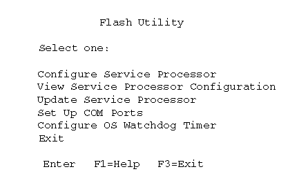
4. Press Ctrl+Alt+Del to restart the system. The adapter configuration Flash Utility menu is displayed:
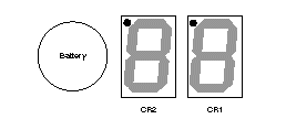
5. Look at the two LED displays on the adapter and check the dot on each LED for the indications listed in the table on page 83.
|
CR1 Dot On |
CR1 Dot Off |
|
Problem indication. Check: |
Normal. Check CR2 Dot. |
|
CR2 Dot Blinking |
CR2 Dot Off |
|
Normal; microcode is |
Microcode is not loaded. |
6. Refer to the configuration data worksheet on page 82 and complete the following steps.
a. Choose Configure Service Processor from the Flash Utility menu and select the port and IRQ you entered in the configuration data worksheet. The utility program writes an SM.INI file to the diskette. This file is used during the device driver installation.
b. Follow the on-screen prompts and choose Setup COM Ports from the Flash Utility menu. Select the COM port I/O addresses and interrupts you entered on the configuration worksheet.
7. Follow the on-screen prompts to exit from the adapter configuration utility program.
8. Replace the system cover.
Go to "Device Driver Installation" for device driver installation instructions.
Device Driver Installation
If the operating system is OS/2, go to "OS/2 Device Driver Installation".
If the operating system is Windows NT, go to "Windows NT Device Driver Installation".
If the operating system is Novell NetWare, go to "Novell NetWare Device Driver Installation".
OS/2 Device Driver Installation
The OS/2 adapter device driver is stored in the C:\OS2 and C:\OS2\DLL directories unless otherwise specified by you. The CONFIG.SYS file is also updated.
To install the adapter device driver and dynamic link library (DLL):
1. Insert the adapter configuration diskette into the diskette drive.
2. Open an OS/2 window.
3. At the OS/2 prompt type: A: and press Enter.
4. At the A: prompt type: OS2\SETUP and press Enter.
5. Follow the menu prompts to complete the installation.
6. Restart the system to activate the device driver.
Refer to the TME 10 NetFinity Version 4.1 documentation for information on the operation and functions of the adapter.
Windows NT Device Driver Installation
The Windows NT adapter device drivers are stored in the Windows NT system directories.
To install the adapter device drivers:
1. Insert the adapter configuration diskette into the diskette drive.
2. Log on with administrator privileges.
3. Open a DOS window.
4. At the DOS prompt type: A: and press Enter.
5. Type CD\NT and press Enter.
6. Type SETUP and press Enter.
The adapter device drivers are loaded and started.
Refer to the TME 10 NetFinity Version 4.1 documentation for information on the operation and functions of the adapter.
Novell NetWare Device Driver Installation
To install the Novell Netware adapter device driver:
1. Insert the adapter configuration diskette into the diskette drive.
2. At the NetWare prompt type: LOAD A:\NETWARE\SETUP and press Enter.
3. Follow the on-screen prompts. If you accept the default choices, the adapter device driver is copied to the hard disk as SYS:\SYSTEM\IBMSPN.NLM, and the AUTOEXEC.NCF file is updated.
4. To load the adapter device driver:
a. Restart the system.
- Or -
b. At the NetWare prompt type: SEARCH ADD path (where path is the path the driver was copied to in step 3) and press Enter.
At the NetWare prompt type: LOAD IBMSPN port-adrs irq (where port-adrs is the port address you selected and irq is the interrupt you selected during the adapter configuration procedure) and press Enter.
The adapter device driver will load without restarting the server.
Refer to the TME 10 NetFinity Version 4.1 documentation for information on the IBM PC Server Advanced Systems Management Adapter operation and functions.
Adapter Cable to System Board Connections
Note
It is easier to connect the cables to the system board and Adapter before you install the Adapter in the system.
PC Server 325
Refer to "System Board".
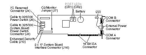
34-pin cable from Adapter (J16) to System Management Cable Connector (J19) on system board.
16-pin cable from Adapter (J8) to Operator Panel Connector (J7) on system board.
Cable from Operator Panel to Adapter (J6).
External Power Control Unit Operation and Indicators
The external power control unit provides power to the system under control of the adapter.
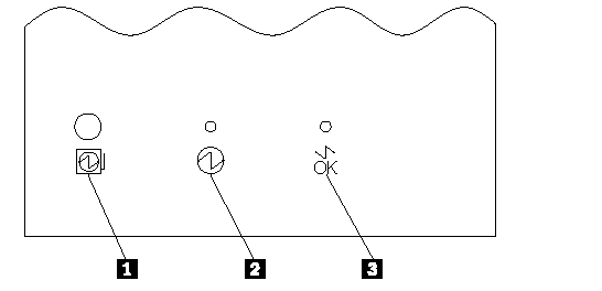
The Power Status LED 2 On indicates power is enabled to the system. The Power Status LED Off indicates power is disabled to the system. The Cable Attached LED 3 On indicates the power unit control cable is connected to the adapter. The Cable Attached LED Off indicates the external power control unit control cable is not connected to the adapter.
If system power from the external power control unit is disabled by the adapter, press the external power control unit power on button 1 to enable system power from the external power control unit.
|
Power Status |
Cable Attached |
Indicates |
Action/ FRU |
|
On |
On |
System power is enabled and the external power control unit signal cable is connected to adapter. |
None |
|
Off |
On |
The adapter has caused system power to be removed and the external power control unit signal |
1. Press the external power control unit power on button 1 to restore system power. |
|
Off |
External power control unit signal cable is not connected to adapter. |
1. Connect the cable to the adapter. |
|
Search Keywords |
| |
|
Hint Category |
Advanced Systems Management, Hardware Maintenance Information | |
|
Date Created |
26-01-98 | |
|
Last Updated |
12-08-98 | |
|
Revision Date |
11-08-99 | |
|
Brand |
IBM PC Server | |
|
Product Family |
PC Server 325 | |
|
Machine Type |
8639 | |
|
Model |
PB0; PT0; PTW; RB0; AAB; 1RY; 2RY; CM0; ZB0; ZBW; ZM0; ZMW; ZS0; ZSW; ZT0; ZTW; ZBR | |
|
TypeModel |
| |
|
Retain Tip (if applicable) |
| |
|
Reverse Doclinks |