
|
34.436 bytes |
Product Information |
Document ID: DDSE-42ZJ43 |
Netfinity 5500 - Input / Output Connectors and Expansion Slots
Applicable to: World-Wide
Input/Output Connectors and Expansion Slots
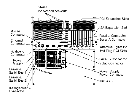
The following illustration shows the expansion slots and the input/output connectors (ports) on the rear of the server.

Keyboard Connector: The keyboard cable connects here.
Mouse Connector: The mouse cable connects here. This port sometimes is called an auxiliary-device or pointing-device port.
Serial Connectors: Serial signal cables for modems and other serial devices connect here to the two 9-pin serial connectors, ports A and B. See "Devices and I/O Ports" for port assignment information. If you are using a 25-pin signal cable, you need a 9-pin-to-25-pin adapter cable.
Video Connector: The monitor signal cable connects here.
NetBAY3: The tower model of the Netfinity 5500 comes with a NetBAY3 attached. You can install devices, such as the IBM EXP10 or a power distribution unit, in the NetBAY3. Refer to "Installing Devices in the NetBAY3" for more information.
Management C Connector: This connector is used to attach a modem that is dedicated to communication with the system management processor.
Parallel Connector: A signal cable for a parallel device, such as a printer connects here.
Universal Serial Bus Connectors: You can attach I/O devices to these two universal serial bus (USB) connectors. You need a 4-pin cable to connect devices to USB 1 or 2.
|
Note |
|
Note |
|
Search Keywords |
| |
|
Document Category |
Diagrams | |
|
Date Created |
09-12-98 | |
|
Last Updated |
09-12-98 | |
|
Revision Date |
09-12-99 | |
|
Brand |
IBM PC Server | |
|
Product Family |
Netfinity 5500 | |
|
Machine Type |
8660 | |
|
Model |
ALL | |
|
TypeModel |
| |
|
Retain Tip (if applicable) |
| |
|
Reverse Doclinks |