|
48.028 bytes |
Parts Information |
Document ID: DDSE-43TRKZ |
Netfinity 3500 - Configuring the Ethernet Controller, Ethernet Cable Specifications and Ethernet Connection Problems
Applicable to: World-Wide
The Netfinity 3500 server comes with an Ethernet controller on the system board. The Ethernet controller provides 10BASE-T and 100BASE-TX support through the RJ-45 connector on the back of the server. When you connect the server to the network, the Ethernet controller automatically detects the data-transfer rate (10 Mbps or 100 Mbps) on the network and then sets the controller to operate at the appropriate rate. That is, the Ethernet controller will adjust to the network data rate, whether the data rate is standard Ethernet (10BASE-T), Fast Ethernet (100BASE-TX), half duplex (HDX), or full duplex (FDX). This process is also known as auto-negotiation. This auto-negotiation occurs without requiring software intervention. The controller supports half-duplex (HDX) and full-duplex (FDX) modes at both speeds.
However, auto-negotiation works only if the hub or switch at the other end of the network also supports auto-negotiation. If the hub or switch does not support auto-negotiation, the speed (10 Mbps or 100 Mbps) will still be detected correctly, but half-duplex mode will always be selected. A full-duplex switch that does not support auto-negotiation will not attach to the Netfinity 3500 server in full-duplex mode. In this case, if you want the network to operate in full-duplex mode, you must manually override the settings to obtain a full-duplex connection. Refer to the Ethernet documentation for additional information.
|
Attention
The 10BASE-T Ethernet and the 100BASE-TX Fast Ethernet cabling in the network must be Category 5 or higher to meet various standards, including electromagnetic compatibility. You must install a device driver to enable the operating system to address the Ethernet controller. Use ServerGuide to install this device driver. Refer to the ServerGuide package for instructions on installing device drivers. |
Fast Ethernet operates at a data rate of 100 Mbps; that is, ten times faster than standard Ethernet. However, except for the different operating speeds, Fast Ethernet and standard Ethernet are structurally identical. Applications and protocols that are currently installed on a standard Ethernet system can be seamlessly migrated to a Fast Ethernet system. (In a very small number of cases, minor tuning might be required to adjust the application to the faster response time of a Fast Ethernet system.) Because of the equivalence of the two types of Ethernet, mixed Ethernet and Fast Ethernet systems also can be designed and implemented.
The bandwidth required at each workstation connected to a server is generally far less than the bandwidth required at the server. This is because the server might have to handle the bandwidth of multiple workstations at the same time. A cost-effective solution to the bandwidth requirements of this type of system is a mixed Ethernet and Fast Ethernet network. This mixed network consists of standard Ethernet connections at the workstations and Fast Ethernet connections at the servers.
The Ethernet controller is a PCI device, and is therefore, a Plug and Play device. You do not have to set any jumpers or configure the controller for the operating system before you use the Ethernet controller.
The Ethernet controller supports the auto-detection mode only. When you install the device drivers and configure the Ethernet controller for use with the operating system, do not select the 10BASE-T mode. To ensure proper operation of the controller, always select the default parameters provided.
|
Notes
1. The Ethernet controller supports the operating systems that the server supports. To find out which operating systems the server supports, go to the following World Wide Web address:
http://www.pc.ibm.com/us/server/ |
If you need additional Ethernet connections, you can install an Ethernet adapter, such as an IBM 10/100 Ethernet adapter. Review the network-adapter documentation for any additional configuration requirements.
|
Note
If you are installing an IBM 10/100 Ethernet adapter, be sure to run the Ethernet diagnostics and record the server's Ethernet configuration information before you install the adapter. |
Ethernet Cable Specifications
The Ethernet controller on the system board provides 10BASE-T and 100BASE-TX support through the RJ-45 connector on the back of your server. When you connect the server to the network, the Ethernet controller automatically detects the data-transfer rate (10 Mbps or 100 Mbps) on the network and then sets the controller to operate at the appropriate rate.
The Ethernet controller supports the auto-detection mode only. When you install the device drivers and configure the Ethernet controller for use with the operating system, do not select the 10BASE-T mode. To ensure proper operation of the controller, always select the default parameters provided.
The following information describes the specifications for the unshielded twisted-pair (UTP) cable that can be used to connect the server to an IEEE Standard 802.3 network.
To connect the server 10BASE-T or 100BASE-TX port to a 10BASE-T or 100BASE-TX port on a repeater, use a UTP cable with RJ-45 connectors at both ends. An EIA/TIA-568 Category 5 cable must be used for 10BASE-T and 100BASE-TX.
|
Attention
The 10BASE-T Ethernet and the 100BASE-TX Fast Ethernet cabling in the network must be Category 5 or higher to meet various standards, including electromagnetic compatibility. |
The cables used in 10BASE-T or 100BASE-TX link segments do not require grounding. However, all devices connected to the cables must be grounded.
Connect the appropriate type of UTP cable to the repeater.
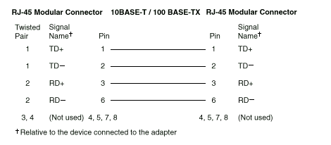
If the port on the repeater is a crossover port (also called an MDI-X port), use a UTP cable that is wired as a straight-through cable.
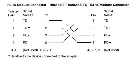
If the port on the repeater is not a crossover port (also known as an MDI port), use a UTP cable that is wired as a crossover cable.
Do not use telephone extension cables to connect the server to a repeater. The wire pairs in those cables are not twisted, and the cables do not meet other requirements for use in a 10BASE-T or 100BASE-TX network. You can identify telephone extension cables by their flat and thin appearance. UTP cables are rounder and thicker than telephone extension cables.
Table 1 describes the specifications for UTP cables used in 10BASE-T and 100BASE-TX link segments.
Cables for these link segments must be certified as EIA/TIA-568 Category 5.
Table 1. Cabling Specifications for 10BASE-T and 100BASE-TX Link Segments
|
Characteristic |
Specification |
|
Cable type |
UTP cable with two twisted pairs
of 22, 24, or 26 AWG wire |
|
Nominal impedance |
100 Ohms |
|
Velocity of propagation |
0.585 c |
|
Maximum attenuation |
For 10BASE-T: 8 to 10 dB
per 100 m at 10 MHz
For 100BASE-TX: 67 dB
per 305 m at 100 MHz |
Cables that have been certified as EIA/TIA-568
Category 5 meet all 10BASE-T and 100BASE-TX specifications. An EIA/TIA-568 Category 5 cable must be used for 10BASE-T and 100BASE-TX.
The cable can contain two to four twisted pairs, but only two of the pairs will be used by the 10BASE-T or 100BASE-TX network.
The c represents the velocity of light traveling in a vacuum, which is 300 000 km/sec (186 400 mi/sec).
|
Notes
AWG = American Wire Gauge
EIA = Electronics Industries Association
STP = shielded twisted pair
TIA = Telecommunications Industries Association |
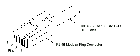
The following figure illustrates the RJ-45 connector.

The following figure illustrates the wiring in straight-through cables.

The following figure illustrates the wiring in crossover cables.

|
Note
For additional information about Ethernet protocols,
refer to your Ethernet documentation. |
Ethernet Connection Problems
|
Note
1. If you use the integrated Ethernet controller, you must use Category 5 cabling. See Ethernet Cable Specifications on page 31 for additional information about Ethernet cable requirements.
2. If you directly connect two workstations (without a hub), or if you are not using a hub with X ports, use a crossover cable (a UTP cable that is wired as a straight-through cable). To determine whether a hub has an X port, check the port label. If the label contains an X, the hub has an X port. |
If the ethernet adapter cannot connect to the network, do the following.
1. Verify that the cable is installed correctly.
2. Check the Ethernet activity light on the front of the server.
|
Note
This light is off when you run the diagnostic programs in the Configuration/Setup Utility program. |
If the Ethernet activity light is off:
a. Make sure that the hub and network are operating, and that the correct device drivers are loaded.
b. There might be a defective Ethernet connector or cable, or a problem with the hub.
3. Make sure that you are using the correct device drivers that come with the server.
4. Check for operating system-specific causes for the problem.
5. Test the Ethernet controller or adapter.
How you test the Ethernet controller or adapter depends on which operating system is being used (see "Configuring the Ethernet Controller")
|
|
Search Keywords |
|
|
Document Category |
Networking |
|
|
Date Created |
04-01-99 |
|
|
Last Updated |
04-01-99 |
|
|
Revision Date |
04-01-2000 |
|
Brand |
IBM PC Server |
|
Product Family |
Netfinity 3500 |
|
|
Machine Type |
8644 |
|
|
Model |
ALL |
|
|
TypeModel |
|
|
|
Retain Tip (if applicable) |
|
|
|
Reverse Doclinks
and Admin Purposes |
|


