
|
100.111 bytes |
Parts Information |
Document ID: DDSE-44JGQG |
Netfinity 3500 - Installing or Removing Drives in Bays 1 through 6
Applicable to: World-Wide
Installing or Removing Drives in Bays 1 through 4:
Use the following procedure for installing a drive in bays 1 through 4. If you want to remove a drive, skip steps 4 through 6 and step 8.
|
Notes
See Drive Specifications for the drive types and sizes that you can install in bays 1 through 4.
You might need to disconnect cables from drives that are already installed in the server. |
1. Read Preinstallation Steps (All Bays) and the instructions that come with the option.
2. Read Termination Requirements.
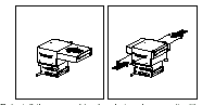
3. Remove the server cover (see Side Access Cover).
4. The server comes with a tray installed in bay 2. If you are installing a 5.25-inch drive in bay 2, you must first remove the tray. To do this, remove the four screws on the bottom of the tray.
5. If a tray is attached to a drive that you intend to install, you must remove the tray before installing the drive. Follow the instructions in the documentation that comes with the drive.
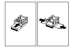
6. Using the instructions that come with the drive, together with these instructions, verify that any switches or jumpers on the drive are set correctly. Change the settings if necessary. For information about termination requirements, see Termination Requirements.
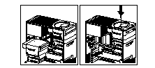
7. Remove the upper drive bracket. See step 3.
8. Touch the static-protective package containing the new drive to any unpainted metal surface; then, remove the drive.
|
Attention
To ensure that the drive functions properly, do not overtighten the screws. |
9. If you are installing a drive in bay 1, 3, or 4, go to step 10.
If you are installing a 3.5-inch drive in bay 2:
a. Loosen the screws on the sides of the tray; then, place the drive on the tray.
|
Note
These are captive screws; therefore, they cannot be removed. |
b. Align the screw holes on the sides of the drive with the screw holes on the sides of the tray; then, tighten the screws.
10. Install the drive into the upper drive bracket so that the power and signal cable connectors are facing the rear of the server. Align the screw holes; then, insert and tighten the four screws.
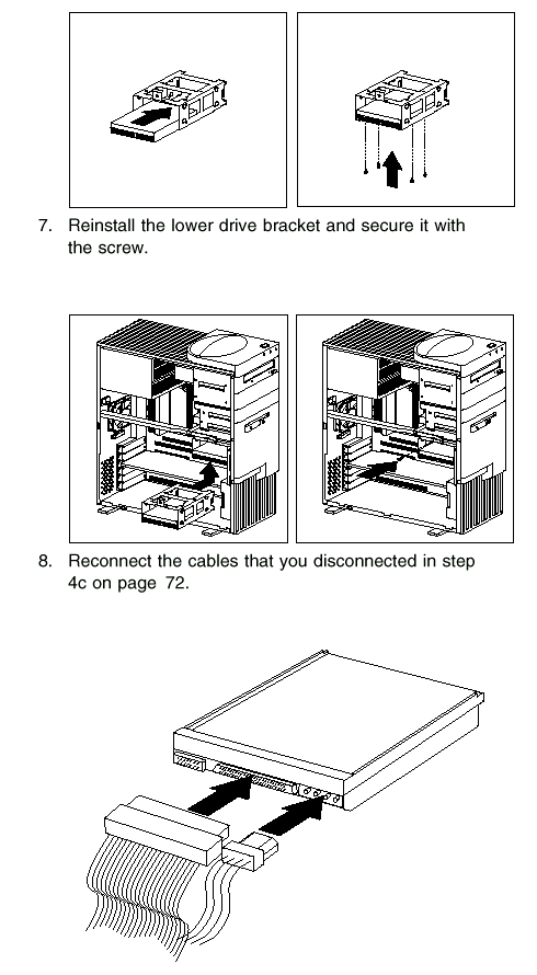
11. Reinstall the upper drive bracket and secure it with screws at the top and bottom.
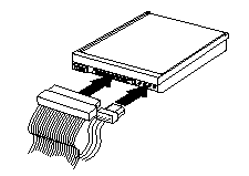
12. Reconnect the cables that you disconnected in step 3c .
|
Note
In some models, the CD-ROM drive has three connectors. Be sure to reconnect the appropriate cables to all three connectors. |
13. If you want to install or remove any other options, do so now. Otherwise, go to Completing the Installation.
Installing or Removing Drives in Bays 5 and 6:
Use the following procedure for installing a drive in bays 5 and 6. If you want to remove a drive, skip steps 4 and 5.
|
Notes
You can install only 3.5-inch hard disk drives in bays 5 and 6.
You might need to disconnect cables from drives that are already installed in the server. |
To install a drive in bays 5 and 6:
1. Read Termination Requirements.
2. Remove the server cover (see Side Access Cover).
3. Remove the lower drive bracket, as described in step 4.
4. Touch the static-protective package containing the new drive to any unpainted metal surface; then, remove the drive.
5. Using the instructions that come with the drive, together with these instructions, verify that any switches or jumpers on the drive are set correctly. Change the settings if necessary. For information about termination requirements, see Termination Requirements.
|
Attention
To ensure that the drive functions properly, do not overtighten the screws. |
6. Install the drive into the lower drive bracket so that the power and signal cable connectors are facing the open side of the server. Align the screw holes and insert two screws on each side of the drive assembly near the bottom, as shown.
|
Attention
1. If the server comes with a drive installed in bay 6, two screws are attached to each side of the drive assembly.
If you remove a drive from bay 6 and install another drive in that bay, use the screws that come with the preinstalled drive.
2. If you are installing a drive in bay 5, turn the drive upside down before you slide it into the bay. This ensures that the drive connector will align with and attach properly to the cable connector.
When you install the four screws that come with the drive, attach them to the drive from the top.
3. If you are installing a drive in bay 6, hold the drive with the connector side up before you slide it into the bay.
If the server is an open-bay model, when you install the four screws that come with the drive, attach them to the drive from the
bottom. |
9. To install a drive in bays 1 through 4, go to Installing or Removing Drives in Bays 1 through 4.
10. If you want to install or remove any other options, do so now. Otherwise, go to Completing the Installation.
|
|
Search Keywords |
|
|
Document Category |
CD-ROM Drives, Diskette Drives, Hard Drives, Optical Drives, Tape Drives |
|
|
Date Created |
27-01-99 |
|
|
Last Updated |
27-01-99 |
|
|
Revision Date |
27-01-2000 |
|
Brand |
IBM PC Server |
|
Product Family |
Netfinity 3500 |
|
|
Machine Type |
8644 |
|
|
Model |
|
|
|
TypeModel |
|
|
|
Retain Tip (if applicable) |
|
|
|
Reverse Doclinks
and Admin Purposes |
|